Sheet conveyer and image recording apparatus

a conveyer and image technology, applied in the direction of article feeders, thin material processing, transportation and packaging, etc., can solve the problems of reducing the efficiency of the conveyer

Active Publication Date: 2022-03-29
BROTHER KOGYO KK
View PDF6 Cites 0 Cited by
  • Summary
  • Abstract
  • Description
  • Claims
  • Application Information

AI Technical Summary

Benefits of technology

[0007]In the sheet conveyer of the former example, when the guide member moves from the closed position to the open position, the paired rollers are always separated from each other while the rollers may not always need to be separated. Each time when the paired rollers are moved to separate from each other, the force to separate the paired rollers from each other may affect the urging member that urges the one of the paired rollers against the other. Thus, the urging member may be abraded, or the resiliency of the urging member may be lowered, and the urging member may be fatigued in a short period of time. In order to restrain the urging member from being fatigued, it may be desirable that the separation of the rollers is restrained as infrequently as possible.
[0010]The present disclosure is advantageous in that a sheet conveyer, in which separation of a roller in paired rollers may be restrained to a minimum frequency, and a movable amount of the roller to be separated from the other roller in the paired rollers may be restricted in a less complicated structure, is provided. Moreover, in the sheet conveyer, the fatiguing effect on the urging member that urges the one of the paired rollers against the other may be reduced, and a jammed sheet may be easily removed.

Problems solved by technology

Thus, the urging member may be abraded, or the resiliency of the urging member may be lowered, and the urging member may be fatigued in a short period of time.
In this regard, however, forming the aperture in the frame and extending the shaft of the roller to reach the frame may complicate the structure in the conveyer and may require a larger space for the sheet conveyer.
Meanwhile, in sheet conveyer of the latter example, the rollers may be moved manually, which may be regarded by the user unhandy.

Method used


Image

  • Sheet conveyer and image recording apparatus
  • Sheet conveyer and image recording apparatus
  • Sheet conveyer and image recording apparatus

Examples


Embodiment Construction

[0024]In the following paragraphs, described with reference to the accompanying drawings will be an embodiment of the present disclosure. It is noted that various connections may be set forth between elements in the following description. These connections in general and, unless specified otherwise, may be direct or indirect and that this specification is not intended to be limiting in this respect. It will be understood that those skilled in the art will appreciate that there are numerous variations and permutations of a sheet conveyer and an image recording apparatus that fall within the spirit and scope of the invention.

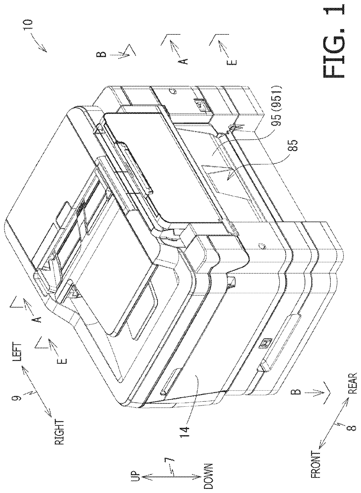
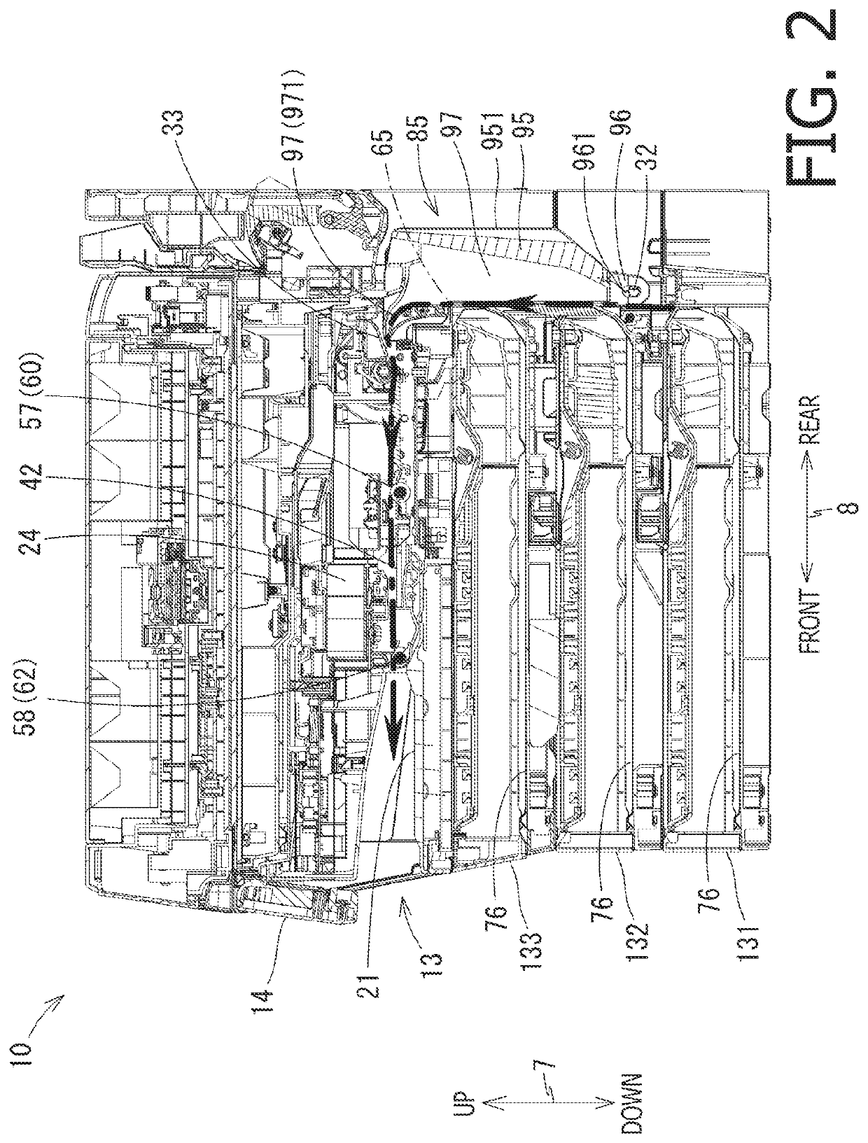
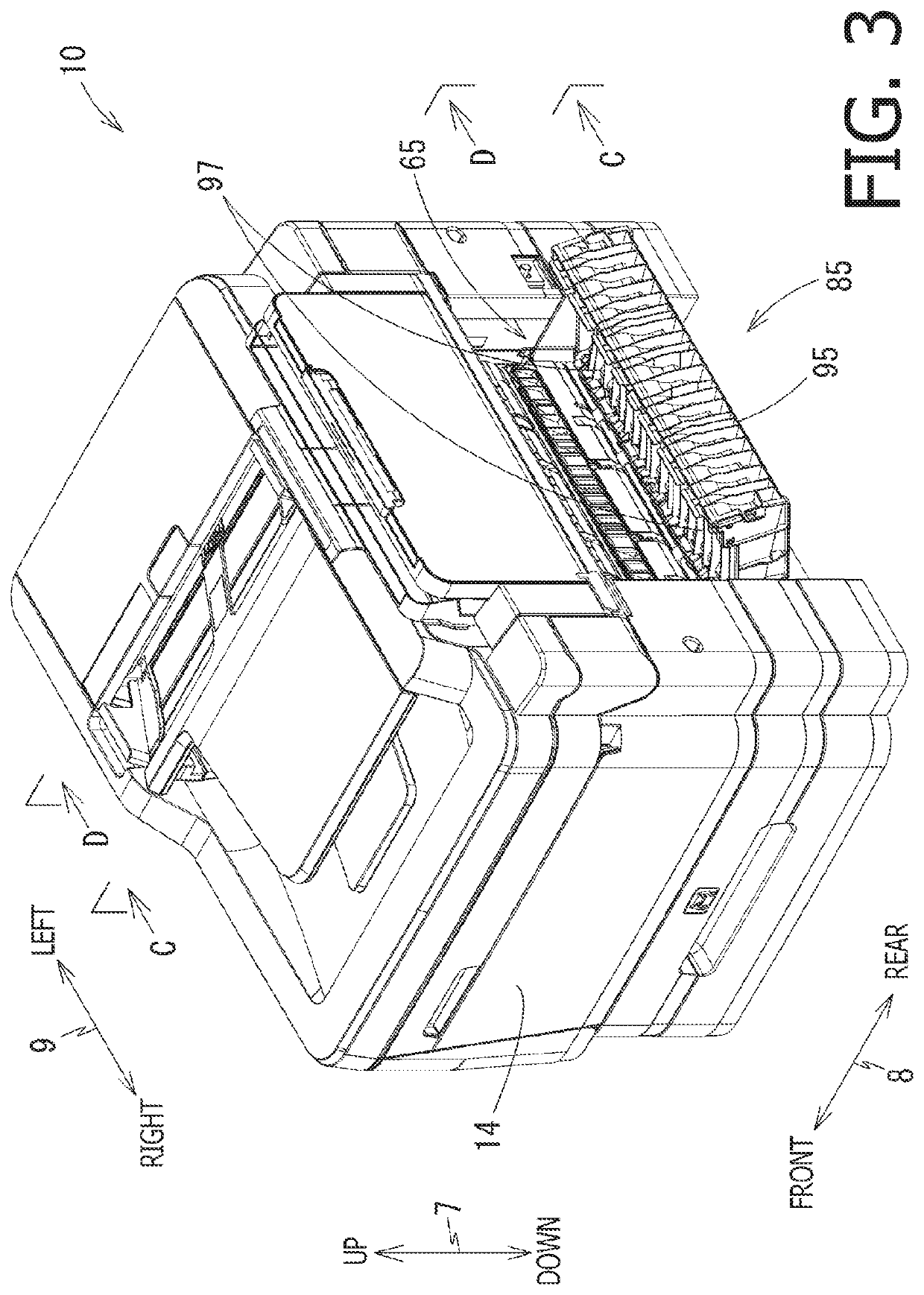
[0025]In the following description, positional relation within the MFP 10 and each part or item included in the MFP 10 will be mentioned on basis of the orientation of the MFP 10 in an operable condition as indicated by the bi-directionally pointing arrows in each drawing. For example, in FIG. 1, a vertical axis between an upper side and a lower side in the drawin...


PUM


Abstract

A sheet conveyer, including a body with a conveyer path, a first roller, a second roller, a roller holder supporting the second roller rotatably, an urging member urging the roller holder, and a guide member, is provided. The guide member is supported rotatably by the body at a position on a side opposite to the first roller across the second roller is pivotable between a closed position and an open position. The roller holder is movable between a first position, where the second roller contacts the first roller, and a second position, where the second roller is separated from the first roller and in which the roller holder contacts the guide member located at the open position. The roller holder located at the second position is restricted by the guide member from moving farther from the first position. The urging member urges the roller holder toward the first position.

Description

CROSS REFERENCE TO RELATED APPLICATION[0001]This application claims priority from Japanese Patent Applications No. 2018-163518 and No. 2018-163881, both filed on Aug. 31, 2018, the entire subject matters of which are incorporated herein by reference.BACKGROUNDTechnical Field[0002]An aspect of the present disclosure is related to a sheet conveyer for conveying a sheet and to an image recording apparatus with the sheet conveyer for recording images on the sheet.Related Art[0003]A sheet conveyer may include paired rollers to convey a sheet along a conveyer path. One of the paired rollers may be urged against the other of the paired rollers by an urging member such as a spring. The paired rollers may nip the sheet in there-between and rotate to covey the sheet.[0004]The sheet conveyer may further have a guide member that forms a part of the conveyer path. The guide member may guide the sheet in the conveyer path. The guide member may be movable between a closed position, in which the gu...

Claims


Application Information

Patent Timeline
Patent Type & Authority Patents(United States)
IPC IPC(8): B65H5/06
CPCB65H5/068B65H2404/144B65H2601/11B65H2601/32B65H5/062B65H2601/321B65H5/38B65H2407/20
Inventor YAMAGUCHI, MASATOMOAOKI, HIROTAKA
Owner BROTHER KOGYO KK
Why Eureka
Try Eureka