Spiral electrodeionization device with flow distribution profiling

a flow distribution and electrodeionization technology, applied in the direction of filtration separation, lighting and heating apparatus, separation processes, etc., can solve the problems of affecting the efficiency or degree of treatment, prone to scaling, and needing to replace beads, so as to achieve the effect of preventing scale formation, enhancing removal of species, and sharpening the separation of differen

US7306709B2Active Publication Date: 2007-12-11IONICS INC
11 Cites 17 Cited by

Patent Information

Authority / Receiving Office
US · United States
Patent Type
Patents(United States)
Current Assignee / Owner
Publication Date
2007-12-11

Smart Images

  • Figure 1
    Figure 1
  • Figure 2
    Figure 2
  • Figure 3
    Figure 3
Patent Text Reader

Abstract

EDI apparatus for demineralizing a liquid flow is assembled in a housing having a cylindrical shape, and includes two metal electrodes, and one or more leafs, each leaf comprising a pair of selectively ion-permeable membranes arranged parallel to each other and spaced apart by spacing elements that allow liquid to flow in the interstitial space between membranes, thus forming an arrangement of dilute and concentrate cells in a desired flow configuration. Spacing elements between membranes, as well as between leaves, can be formed of inert polymer material, ion exchange beads, ion exchange fibers, a combination of two or more these elements, or a porous media incorporating one or more of such elements as an intrinsic part. An inner or central electrode and an outer or perimeter electrode establish a generally uniform and radially-oriented electrical or ionic current between the inner and the outer electrodes, across the helical flow spaces defined by the membrane / spacer windings. One or both electrodes may include a pocket, and the adjacent flow cells lie parallel to the electrode and free of shadowing and field inhomogeneity around a full circumference of the electrode. Flow paths within the helical cells are defined by barrier seals, which may form a path-lengthening maze, while unfilled cell regions may disperse or collect flow within a cell and define pressure gradients promote directional flows. Impermeable barriers between membranes further prevent the feed and concentrate flows from mixing. In various embodiments, seals along or between portions of the flow path may define a multi-stage device, may define separate feed and / or concentrate flows for different stages, and / or may direct the feed and concentrate flows along preferred directions which may be co-current, counter-current or cross-current with respect to each other within the apparatus.
Need to check novelty before this filing date? Find Prior Art

Description

REFERENCE TO RELATED APPLICATIONS

[0001] This application claims the benefit of earlier-filed PCT International Application US2004 / 034909 filed Oct. 20, 2004, which claimed priority of U.S. Provisional Application Ser. No. 60 / 512,661 filed Oct. 20, 2003.BACKGROUND

[0002] The present invention relates to methods and devices for demineralizing fluids, and relates to filtration or treatment cartridges or modules, having a generally cylindrical aspect and constructed with plies of spirally wound selectively-permeable membranes. It particularly relates to electrodialysis and electrodeionization devices, wherein the membranes possess ionic selectivity, and the device includes electrodes for inducing transport of species across the membranes by ionic conduction.

[0003] In general, electrodialysis (ED) and so-called electrodeionization (EDI) devices operate by providing a structure that arranges flow channels such that a flow of a feed fluid that is to be treated is channeled between two ion exch...

Examples

Embodiment Construction

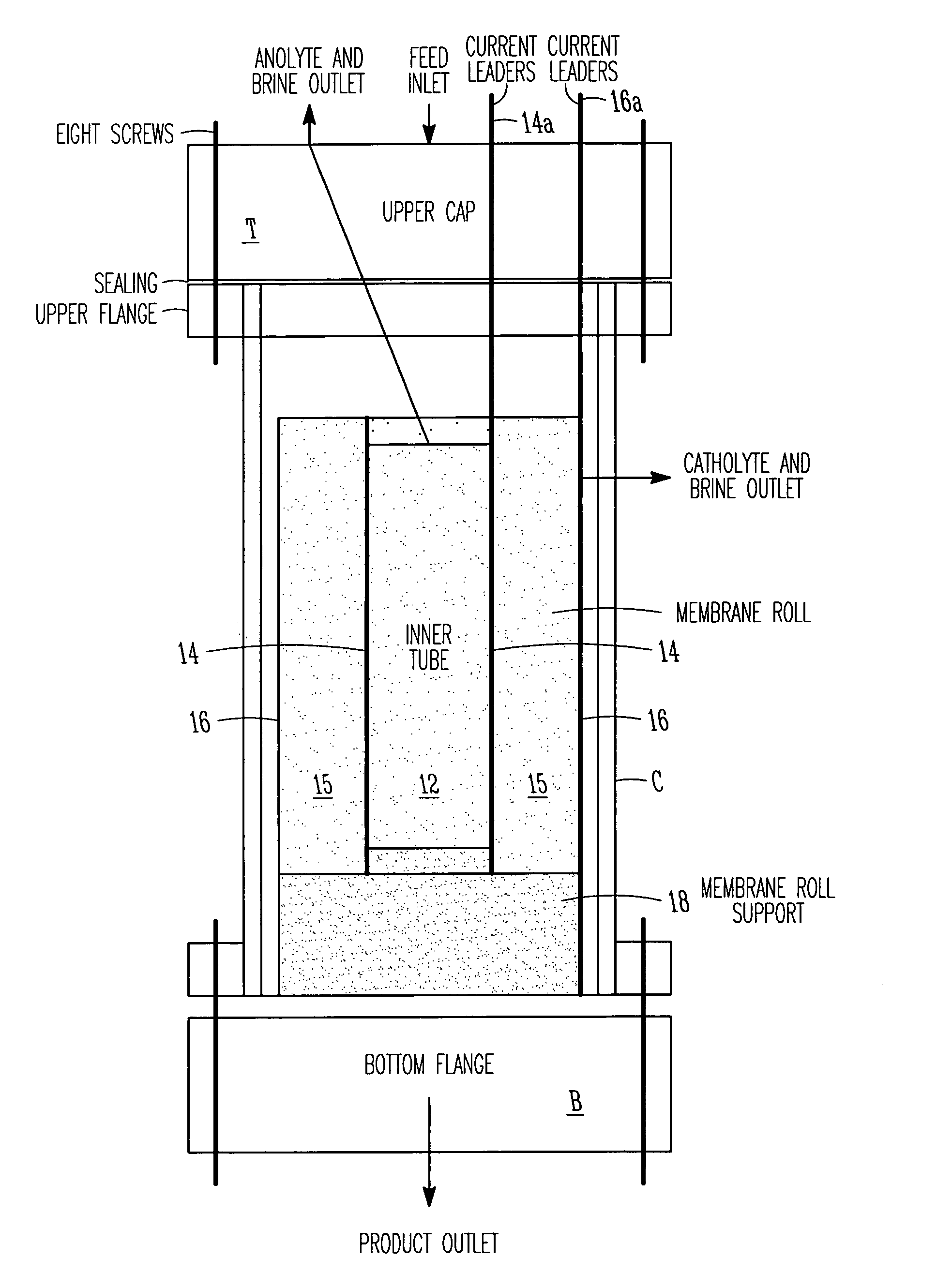
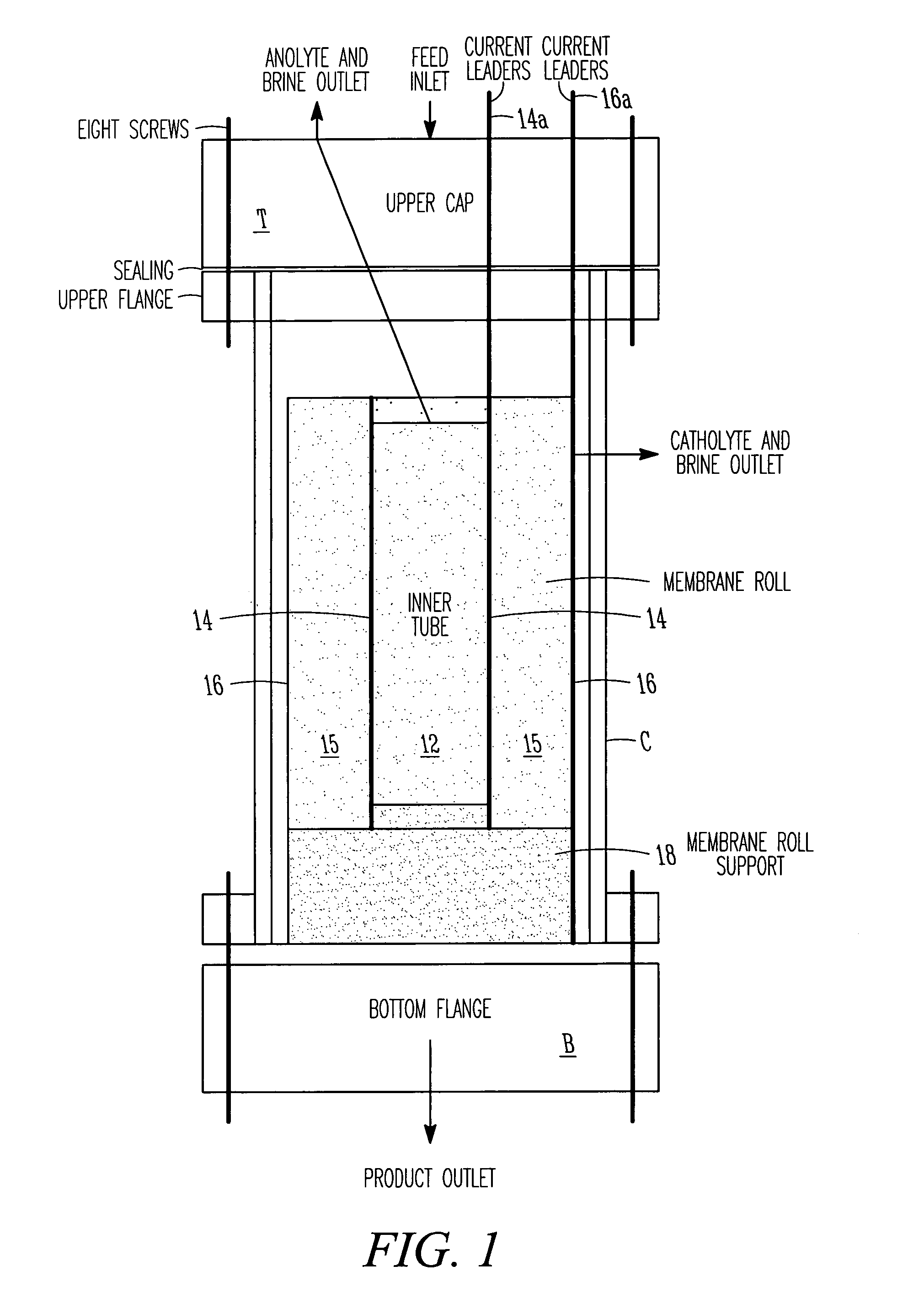
[0044]FIG. 1 is a schematic plan view of a first embodiment 10 of a cylindrical EDI apparatus in accordance with the present invention, showing general layout of components. The EDI apparatus 10 includes a housing illustratively comprised of a bottom flange plate B, a top flange plate T and a cylindrical body C that together define a generally cylindrical vessel or fluid-confining enclosing chamber. A membrane roll 15, of which several examples are described below, is wound around a central core 12 within the housing. Illustratively, a membrane roll support 18, the structure of which may take various forms, supports the membrane roll. An inner electrode 14 surrounds the central core 12, and is coupled to a first current leader 14a for connection to an external power source, and an outer electrode 16, coupled to a second current leader 16a, substantially surrounds the membrane roll 15. The membrane roll is wound in a spiral in the annular space between the two electrodes 14, 16. With...