System and Method for Separating a Fluid Stream

a fluid stream and system technology, applied in the direction of separation process, liquid displacement, borehole/well accessories, etc., can solve the problem of increasing the size/volume of the slug catcher, and achieve the effect of improving the separation between heavy and light liquids

Active Publication Date: 2008-11-06
SHELL USA INC
View PDF20 Cites 16 Cited by
  • Summary
  • Abstract
  • Description
  • Claims
  • Application Information

AI Technical Summary

Benefits of technology

[0017]In the event that the system comprises a plurality of downwardly extending tubes, there is suitably further provided one or more transverse fluid connectors between the downwardly extending tubes, at a height between the first and second heights, preferably at least one above the third height. Such so-called sub-headers promote the equilibration of liquid and interface levels throughout the plurality of tubes. The movement of liquid in the slug catcher will be stabilized and separation between heavy and light liquid is expected to improve.

Problems solved by technology

The conventional solution to this problem would be to arrange the outlet for light liquid at a higher position, however this has the disadvantage that the size / volume of the slug catcher increases.

Method used


Image

  • System and Method for Separating a Fluid Stream
  • System and Method for Separating a Fluid Stream
  • System and Method for Separating a Fluid Stream

Examples


second embodiment

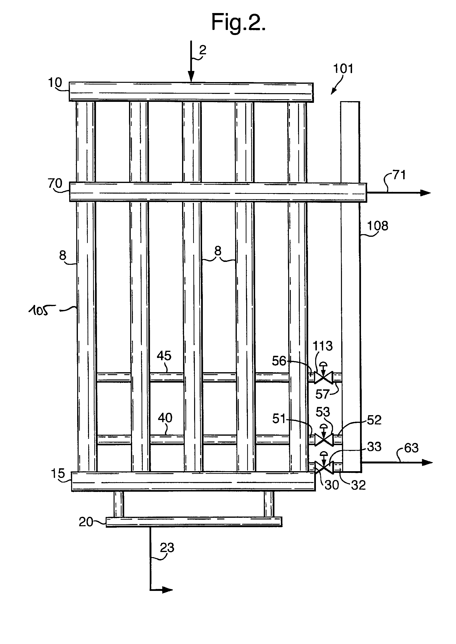
[0051]Reference is made to FIG. 2, showing a system 101 of the invention. FIG. 2 is a top view onto a slug catcher 105 generally similar to the slug catcher 5 of FIG. 1, and the same reference numerals have been used to designate the same or similar parts. The main difference is that one of the tubes, tube 108, is arranged to function as collector vessel, so that no separate collector vessel (like 60 in FIG. 1) needs to be installed. The collector tube 108 is not connected to the inlet header 10. Alternatively, e.g. when adapting an existing slug catcher according to the present invention, fluid communication with the inlet header can be blocked. The collector tube 108 is connected to the gas header 70, and via conduits 32,52,57 equipped with controllable valves 33,53,113 to the condensate header 15, first and second condensate sub-headers 40,45, respectively.

[0052]The control circuit of system 101 is not shown in FIG. 2 for the sake of clarity, and it shall be clear that it can be ...

third embodiment

[0053]Reference is made to FIG. 3. The Figure shows a system 201 of the present invention system in side view. The system 201 is generally similar to the one discussed with reference to FIG. 1, and like reference numerals are used for the same or similar parts.

[0054]In side view it is shown that the tubes 8 slope downwardly at a very small angle. Typical is an angle with the horizontal of 0.5-1 degrees. The downstream part 208 can have a larger slope as shown, e.g. 1-5 degrees. The angles are exaggerated in FIG. 3. The inlet header is not shown. Tubes can have a diameter of 1-2 meter, and the total volume of a slug-catcher can be 1000-3000 m3.

[0055]Only one condensate sub-header 45 is arranged, above a predetermined maximum water level so that no control valve for conduit 57 is provided. The control circuit is largely similar to that of FIG. 1, here a separate low level controller 263 for the collector vessel 60, controlling valve 264, is shown, for separate minimum level safeguardi...


PUM

PropertyMeasurementUnit
angleaaaaaaaaaa
angleaaaaaaaaaa
total volumeaaaaaaaaaa

Abstract

A system (1) for separating a fluid stream (2) comprising gas, a light liquid and a heavy liquid, the system comprising a separation vessel (5) that is arranged to define a downwardly extending separation space and comprises a downwardly sloping tube (8), the separation space having an inlet (10) for the fluid stream at a first height, an outlet (20) for heavy liquid at a second height below the first height, an outlet (30) for light liquid at a third height between the first and second heights, an outlet (70) for gas above all outlets for liquid, wherein a further outlet (51, 56) for light liquid is provided at a fourth height between the first and third heights, and wherein at least the outlet at the third height is provided with a control valve (33) that is operative to open and close in dependence of the type of liquid in the pipes at that level, and a method of separating a fluid stream comprising gas, a light liquid and a heavy liquid in such a system, wherein an indication of height of an interface between heavy and light liquid in the separation vessel is obtained and the control valve at the third outlet is operated in dependence on the height of the interface.

Description

FIELD OF THE INVENTION[0001]The present invention relates to a system and method for separating a fluid stream comprising gas, a light liquid and a heavy liquid.BACKGROUND OF THE INVENTION[0002]In the production line from hydrocarbon wells, in particular gas wells, often a multiphase fluid is transported. The fluid typically comprises gas such as natural gas, light liquid such as hydrocarbon oil or condensate, and heavy liquid, such as water (brine). Further the fluid can contain some solids. The flow rate of the produced fluid can vary, as can the phase composition.[0003]Liquids are normally separated from the gas in so-called separator tanks. However, the gas and liquid may have to travel through long pipelines before separation can take place. In that case the liquid can build up in the pipeline to large slugs. Slugs can also result from a so-called pigging operation of the pipeline, in which a pigging device (for example a sphere) is moved through the pipeline, thereby pushing t...

Claims


Application Information

Patent Timeline
Patent Type & Authority Applications(United States)
IPC IPC(8): B01D17/032B01D17/12B01D17/025E21B43/34
CPCB01D17/00E21B43/34B01D17/0208B01D17/0214B01D17/12
Inventor CHIENG, JILL HUI CHIUNVAN DIJK, FREDERICK JAN
Owner SHELL USA INC
Why Eureka
Try Eureka