System and method for gas separation

a gas separation and gas technology, applied in the field of gas separation, can solve the problems of increasing the pressure within the system, significant high-purity separation is difficult to achieve, and the power consumption of the separation nozzle is significant relative to the separation achieved, so as to reduce the cost of processing the gas

Active Publication Date: 2013-01-22
CASELLA WASTE SYSTEMS
View PDF40 Cites 18 Cited by
  • Summary
  • Abstract
  • Description
  • Claims
  • Application Information

AI Technical Summary

Benefits of technology

[0012]The present invention provides a system and method for the separation of gaseous components from gaseous mixtures in order to control emissions and treatment of the gaseous components. In one embodiment, the invention makes use of a fan or gas moving device to first separate component gases from larger volume gas streams and then process smaller gas streams for capture or treatment of those gases. The separation is afforded by the reactive centrifugal forces imposed as the gas moves from the center of the fan toward the outer periphery where heavier gases are forced to the outer regions of the fan housing while lighter gases remain closer to the fan axis. The separation of gas streams based on molecular weight of the gas provides the opportunity to treat or interact with only a portion of a gas stream to reduce the cost of processing the gas.

Problems solved by technology

A disadvantage of this system is that the sulfur containing byproducts can deposit in the transfer lines and can cause an increase in pressure within the system.
Most of these reactants form a substantial part of the cost for control of emissions, in addition to the high cost to cause the reactants and the gases to come into intimate contact with each other so that the desired reactions can take place.
Under standard conditions, significant high-purity separation is difficult to achieve unless the rotational velocity is extremely high.
The power consumption of separation nozzles is significant relative to the separation achieved.
Vortex chamber separators have the disadvantage of relatively lower separating efficiency relative to the energy requirement, primarily because of high flow resistance in the vortex chamber and also the use of multi-chamber systems with relatively high volume.

Method used


Image

  • System and method for gas separation
  • System and method for gas separation
  • System and method for gas separation

Examples


Embodiment Construction

[0028]As used throughout the disclosure, the term “mechanical draft fan”, unless otherwise indicated, refers to large diameter centrifugal fan for moving air or other gases.

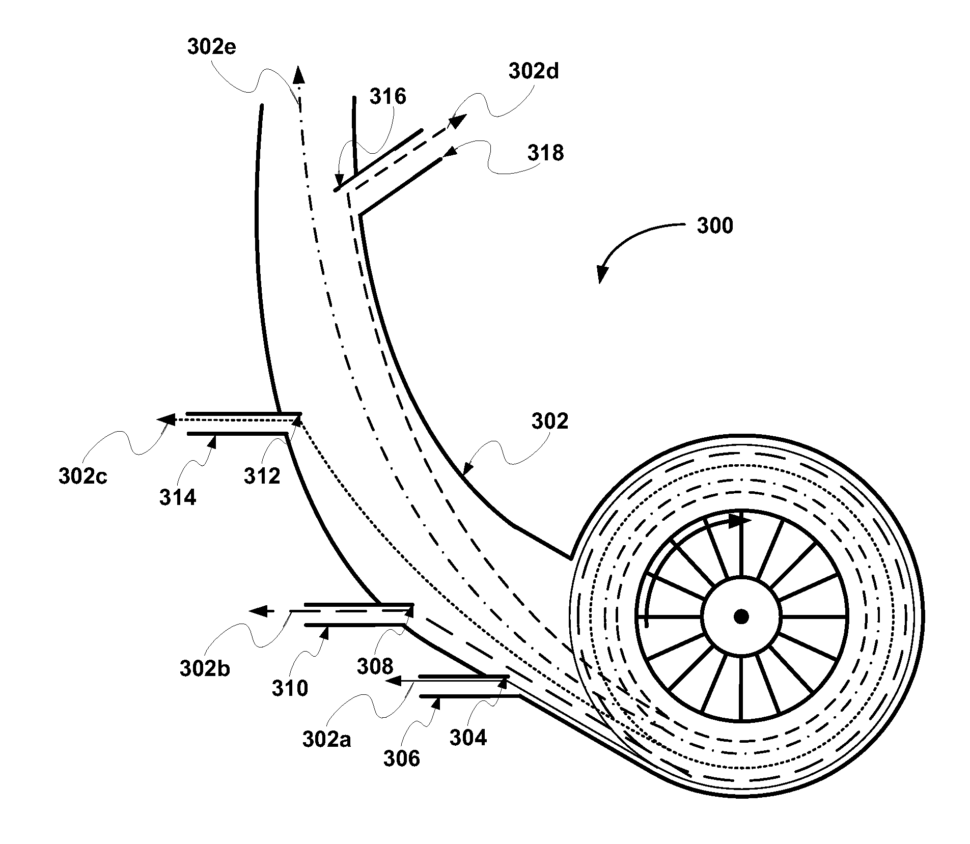
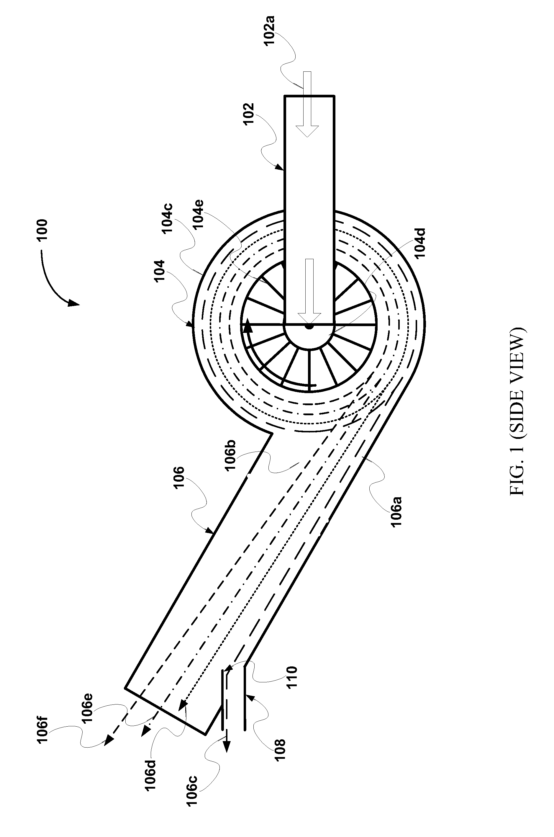
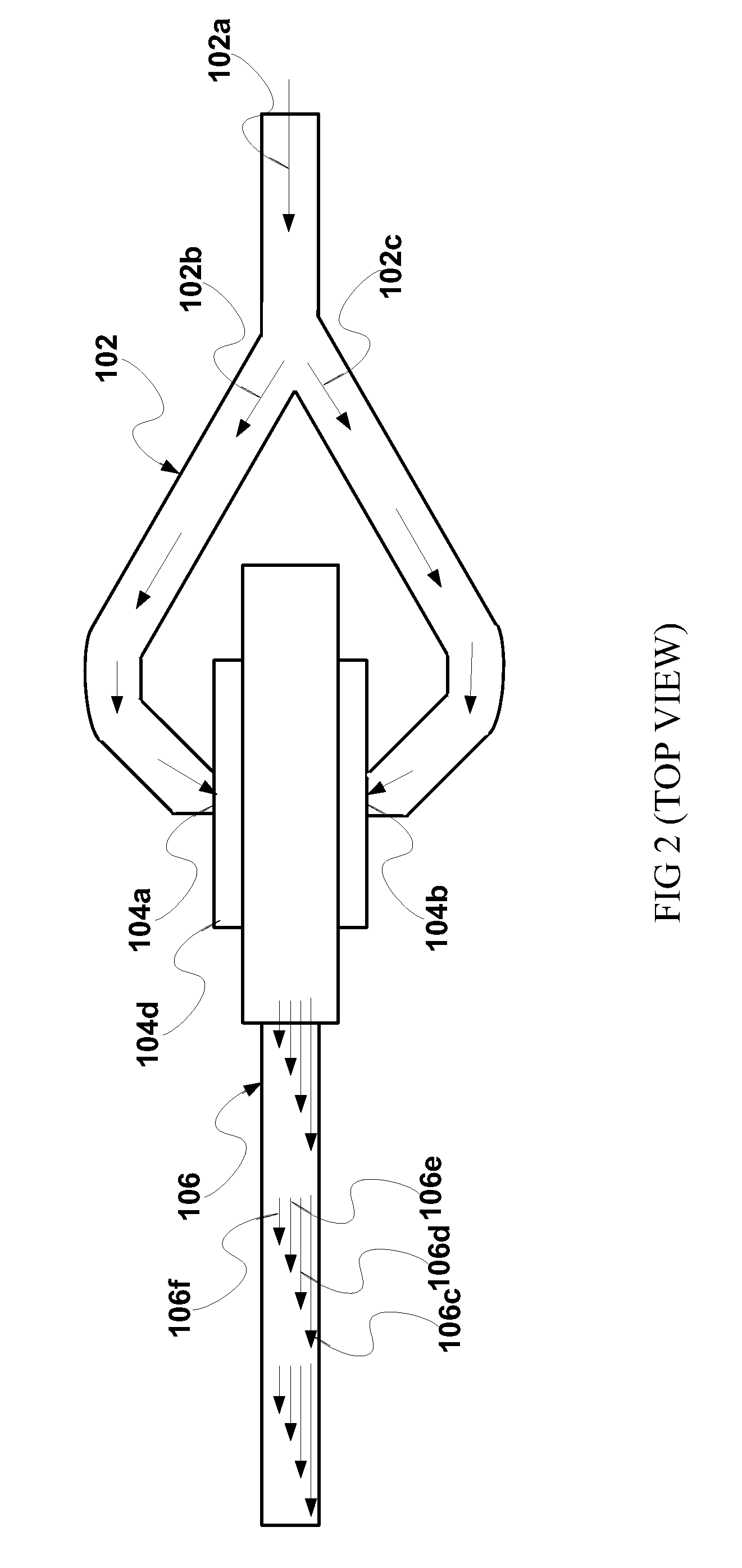
[0029]Referring now to the drawing, and more particularly, to FIG. 1, there is shown a system for separating gaseous components from a mixture of gases, generally designated 100, which comprises the preferred embodiments of the present invention. System 100 includes an inlet duct 102, an mechanical draft fan 104, an outlet duct 106, a discharge outlet duct 108, and a baffle 110. Exemplary mechanical draft fans include induced draft fan, forced draft fan, balanced draft fan, and the like.

[0030]In one embodiment of the present invention, inlet duct 102 is connected in a conventional manner to a gas source, such as a landfill. Inlet duct 102 carries a gas stream 102a (e.g. landfill gas) from the gas source to inlets 104a-b of mechanical draft fan 104, a shown in FIG. 2.

[0031]Mechanical draft fan 104 is positioned be...


PUM

PropertyMeasurementUnit
lengthaaaaaaaaaa
interior angleaaaaaaaaaa

Abstract

The present invention relates to a system and method for the separation of gaseous components from gaseous mixtures in order to control emissions and treatment of the gaseous components. In one embodiment, the system makes use of a fan or gas moving device to first impose centrifugal forces on gas streams as the gas moves from the center of the fan toward the periphery of the fan housing. Heavier gases are forced to the outer regions of the fan housing while lighter gases remain closer to the fan axis. The heavier gases and lighter gases exiting the fan housing flow into a duct at different flow rates, and the heavier gases are diverted from the larger volume gas streams and then processed.

Description

FIELD OF THE INVENTION[0001]The present invention generally relates to gas separation and, more particularly, is concerned with systems and method for gas separation for control of emissions and treatment of gas constituents.BACKGROUND OF THE INVENTION[0002]Release of waste industrial gases, landfill gases, and / or combustion products or byproducts to the atmosphere may be regulated for safety or to protect the environment and, therefore, have limits established on the quantity of one or more gases that may be released to the environment. Major components of landfill gas are methane, carbon dioxide and nitrogen. There are also minor amounts of oxygen, other organic compounds, halides and hydrogen sulfide. Landfill gases, which present a potential renewable energy source, are believed by many scientists to contribute to the greenhouse effect. At present, landfill gases are dealt with by venting to the atmosphere; burning in boilers; flaring; fueling gas turbine or internal combustion ...

Claims


Application Information

Patent Timeline
Patent Type & Authority Patents(United States)
IPC IPC(8): B01D45/12
CPCB01D53/24B01D2256/10B01D2256/12B01D2256/245B01D2257/304B01D2257/502B01D2257/504B01D2257/55Y02E50/346Y02E50/30
Inventor MORRISON, GARRETT L.
Owner CASELLA WASTE SYSTEMS
Why Eureka
Try Eureka