Safety device for sliding door

a safety device and door technology, applied in the direction of door/window fittings, finger guards, constructions, etc., can solve the problem of inadvertent finger injury and other problems, and achieve the effect of preventing the occurrence of large noise and preventing finger injury

Active Publication Date: 2022-03-29
TOK BEARING CO LTD
View PDF13 Cites 0 Cited by
  • Summary
  • Abstract
  • Description
  • Claims
  • Application Information

AI Technical Summary

Benefits of technology

[0031]According to this structure, when the sliding door is started to be closed vigorously, the contact face of the feed plate collides with the outer peripheral surface of the disk part in the disk roller vigorously with a predetermined strength or more, and the disk roller is moved to a direction (C direction) of a resultant vector of the closing direction of the sliding door (substantially horizontal direction: A direction) and a direction orthogonal to the contact face of the feed plate (B direction), the shaft part is moved from the inside of the slow movement groove to the inside of the stopper part of the lock groove, and the disk roller is soon nipped between the stopper part of the lock groove and the contact face of the feed plate to automatically become in a lock state, inhibiting further movement of the feed plate to the closing side together with the sliding door. Thus, it is possible to prevent a finger or the like from being inadvertently caught in opening / closing operation of the sliding door and prevent the occurrence of a large noise.

Problems solved by technology

These sliding doors have a problem in which a finger or the like is inadvertently injured because of being caught between a frame on an opening side and a frame on a sliding door when the sliding door is opened and closed.

Method used


Image

  • Safety device for sliding door
  • Safety device for sliding door
  • Safety device for sliding door

Examples


embodiments

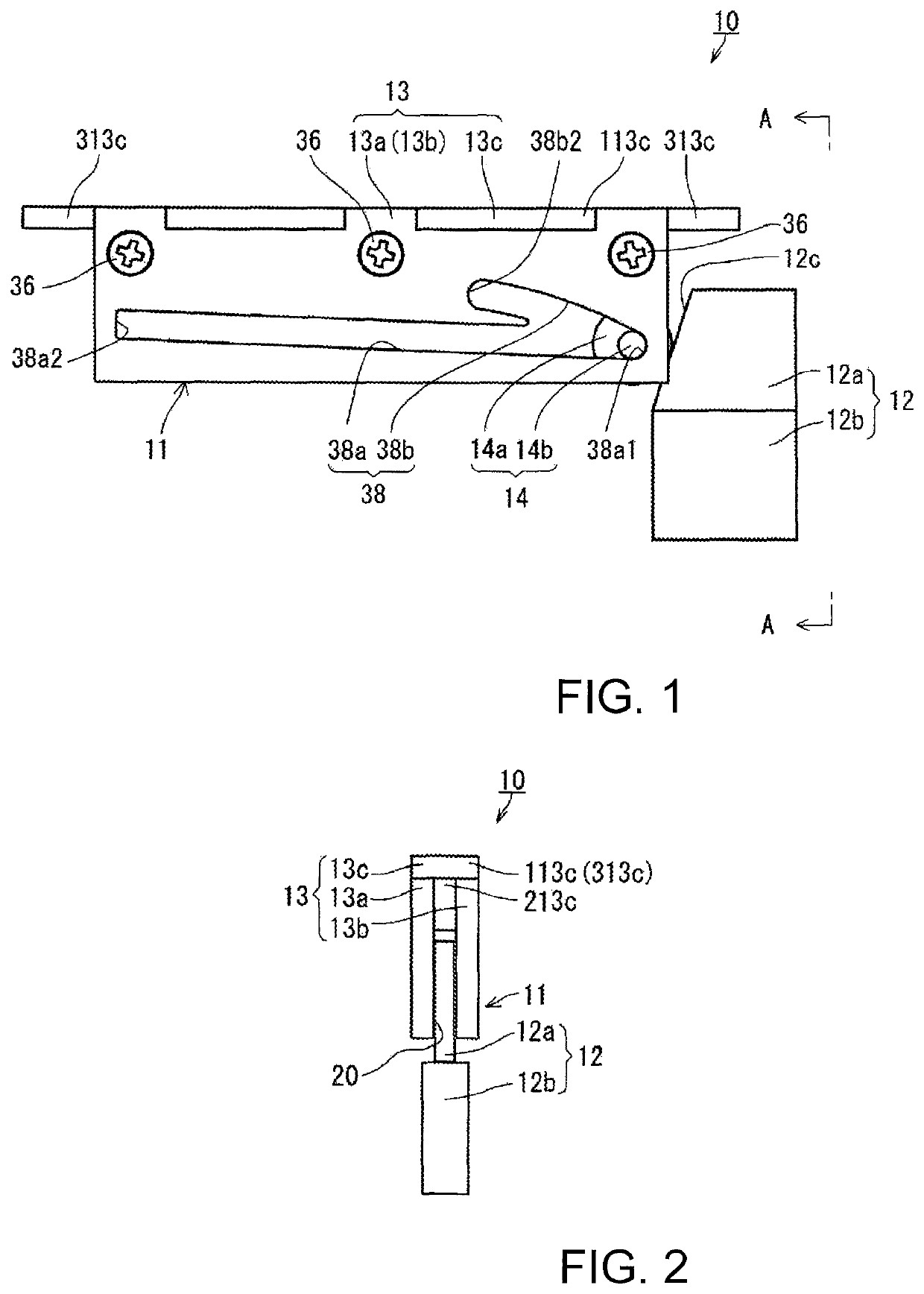
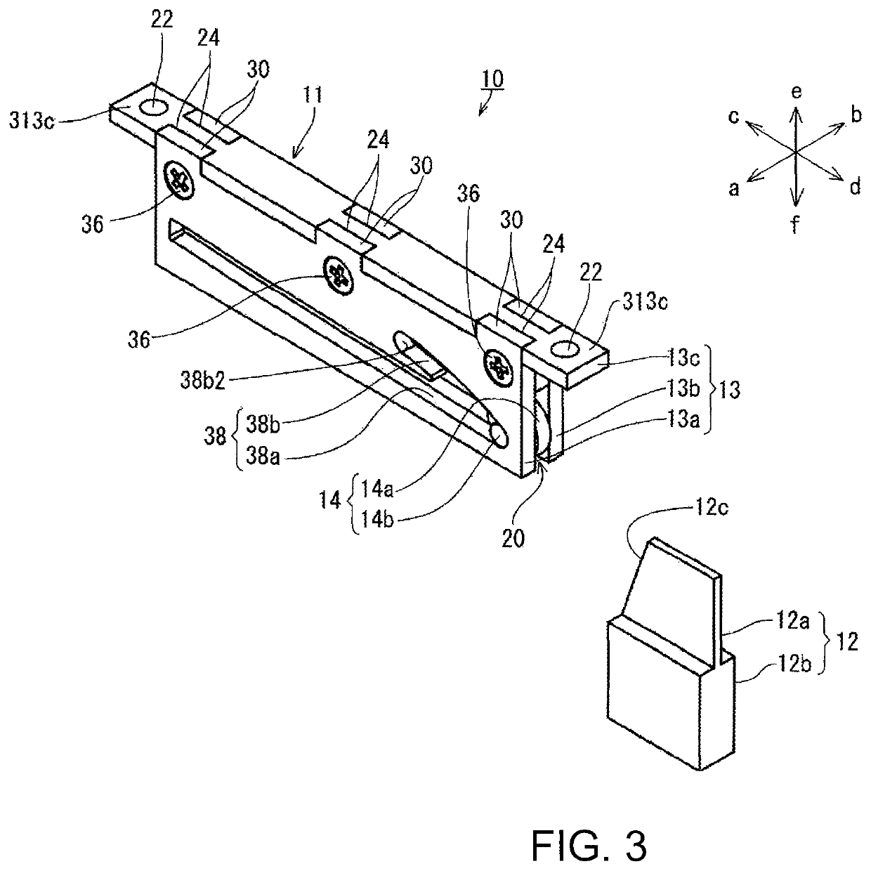
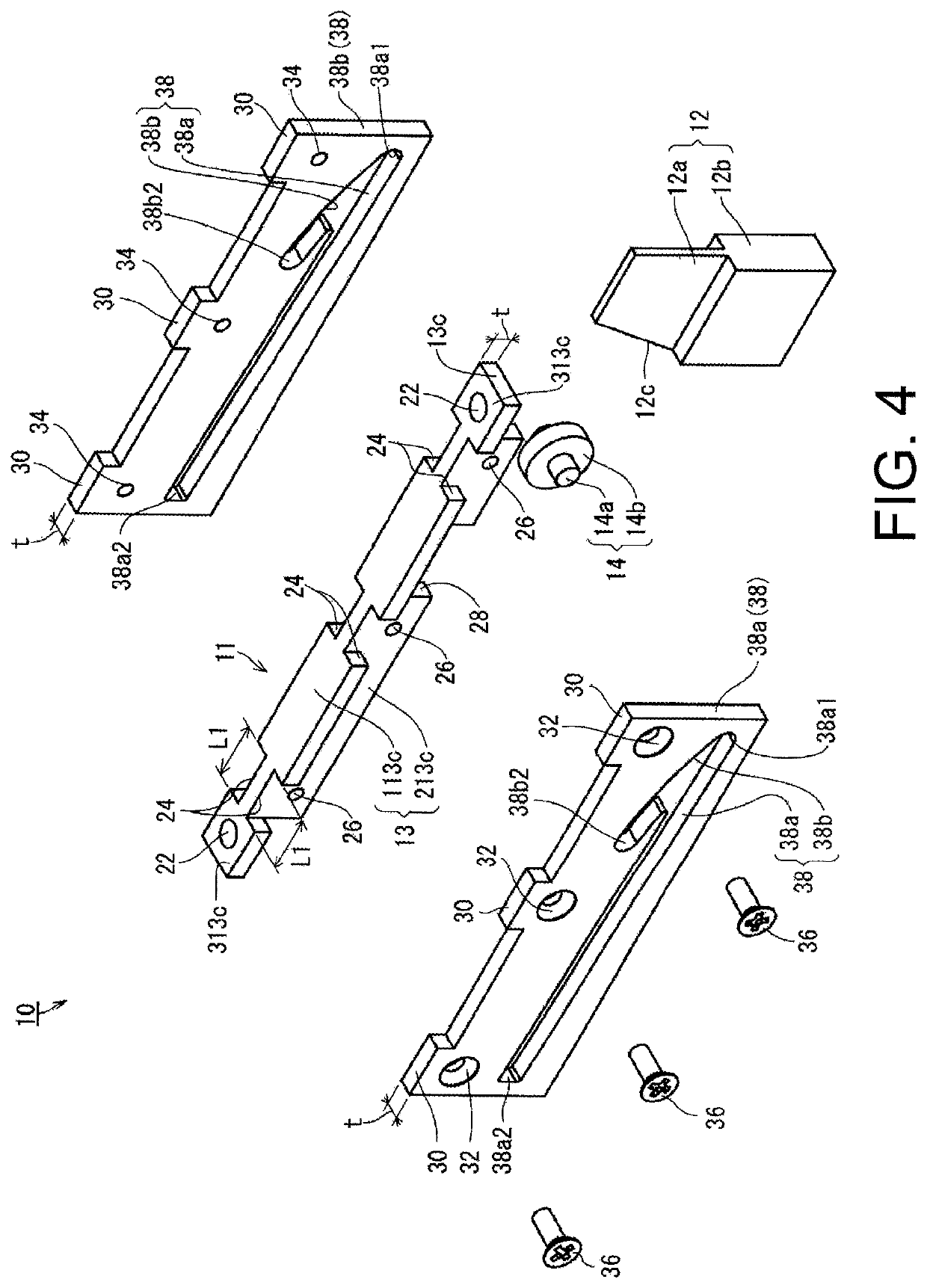
[0053]FIG. 1 to FIG. 4 depict a first embodiment of a safety device 10 for a sliding door (hereinafter simply referred to as a safety device 10) according to the present invention. FIG. 1 is a side view of the safety device 10 viewed from the front, FIG. 2 is a side view of the safety device 10 viewed from a direction of an A-A line of FIG. 1, FIG. 3 is an external perspective view of the safety device 10, and FIG. 4 is an exploded perspective view of the safety device 10. In the following description, description is made by taking, in FIG. 3, an arrow a-b direction as a front-rear direction of the safety device 10, an arrow c-d direction as a left-right direction of the safety device 10, and an arrow e-f direction as an up-down direction of the safety device 10. Also, description is made by taking an arrow c direction as a fully-closed position side, an arrow d direction as a fully-open position side, and, furthermore, a surface depicted in FIG. 1 as a front side.

[0054]In FIG. 1 to...


PUM


Abstract

[Problem] To provide a safety device for a sliding door with which finger pinching can be automatically prevented without manually operating a stopper, and which can be smoothly closed without a resistance that acts when closing the sliding door. [Solution] A safety device for a sliding door is provided with a guide frame 11 and a feed plate 12 that are mounted on the opening side and the sliding door side, respectively, so as to face each other. A low-speed movement groove 38a and a lock groove 38b are provided on the guide frame 11 side. A contact face 12c that is inclined to contact a disk roller is provided on the feed plate 12 side. In addition, when the feed plate 12 collides with the disk roller 14 at a force stronger than or equal to a prescribed value, the shaft 14b of the disk roller 14 is moved from inside the low-speed movement groove 38a to inside the lock groove 38b and the movement of the disk roller 14 in the left-right direction is locked.

Description

TECHNICAL FIELD[0001]The present invention relates to safety devices for sliding doors and, in particular, to a safety device for a sliding door which opens and closes to left and right, the device for preventing a finger or the like from being injured because of being caught between a frame on an opening side and a frame on a sliding door side when the sliding door is opened and closed.BACKGROUND ART[0002]In general, as a sliding door which opens and closes to left and right, a double sliding door, a single sliding door, and so forth have been known. These sliding doors have a problem in which a finger or the like is inadvertently injured because of being caught between a frame on an opening side and a frame on a sliding door when the sliding door is opened and closed.[0003]Thus, various safety device have been suggested for preventing a finger or the like from being injured because of being caught between the frame on the opening side and the frame on the sliding door side when th...

Claims


Application Information

Patent Timeline
Patent Type & Authority Patents(United States)
IPC IPC(8): E05F5/00E06B7/36
CPCE05F5/003E06B7/36E05Y2201/412E05Y2201/688E05Y2800/296E05Y2800/41E05F7/04
Inventor TOMISAWA, TOSHIKI
Owner TOK BEARING CO LTD
Why Eureka
Try Eureka