Storage structure for vehicle

a technology for storage structures and vehicles, applied in passenger spaces, roofs, transportation and packaging, etc., can solve the problems of burdening users and the finger used to press buttons, and achieve the effect of minimizing time and effort for assembly

Active Publication Date: 2015-01-01
TOYOTA BOSHOKU KK +1
View PDF0 Cites 0 Cited by
  • Summary
  • Abstract
  • Description
  • Claims
  • Application Information

AI Technical Summary

Benefits of technology

[0007]The present invention provides a storage structure for a vehicle that can prevent a situation in which the finger of the user contacts the storage part when the retracted state of the storage part is cancelled by pressing a button.
[0009]In this embodiment, the storage part cannot be moved to the use position by pressing the button from its initial position, and the storage part is moved to the use position by restoring the button from the pressed state to its initial position. Thus, the direction in which the finger of the user is moved to operate the button and the direction in which the storage part moves are not opposite to each other. Thus, even when the storage part pops out forward, the finger of the user can be prevented from contacting the storage part. In addition, because the user can stop pressing the button any time the user likes, the storage part is easy to use for the user.
[0011]According to the above aspect, because the first lock state, which is used as a normal lock state, is cancelled and the second lock state, which is easier to cancel than the first lock state, is instead created by pressing the button, the entire unlocking operation can be carried out smoothly.
[0013]According to the above aspect, because the members that are used to cancel the first lock state are also used to create the second lock state, the number of parts is small and the time and effort for the assembly can be minimized.
[0014]According to the aspect of the present invention, a situation in which the finger of the user contacts the storage part when the retracted state of the storage part is cancelled by pressing a button can be prevented.

Problems solved by technology

Thus, there is a possibility that the nail of the finger that is used to press the button is caught by the storage part when the storage part pops out forward and the user feels uncomfortable.
However, the fact that the contact between the storage part and the finger cannot be avoided unless the storage part is used in this way might impose a burden on the user.

Method used


Image

  • Storage structure for vehicle
  • Storage structure for vehicle
  • Storage structure for vehicle

Examples


Embodiment Construction

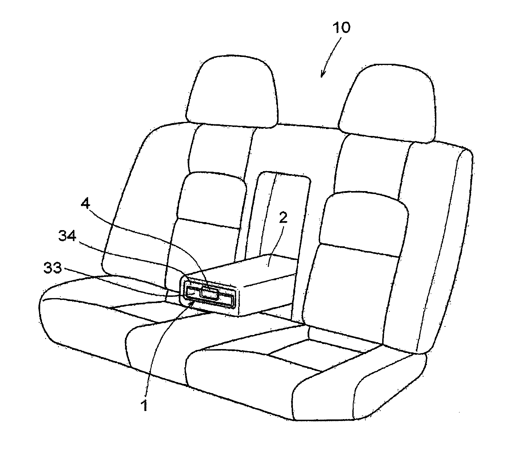
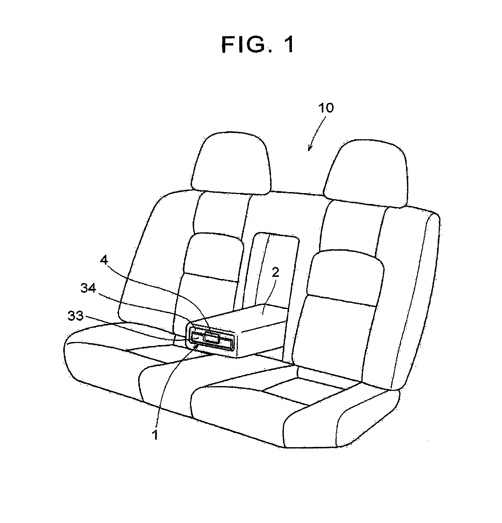
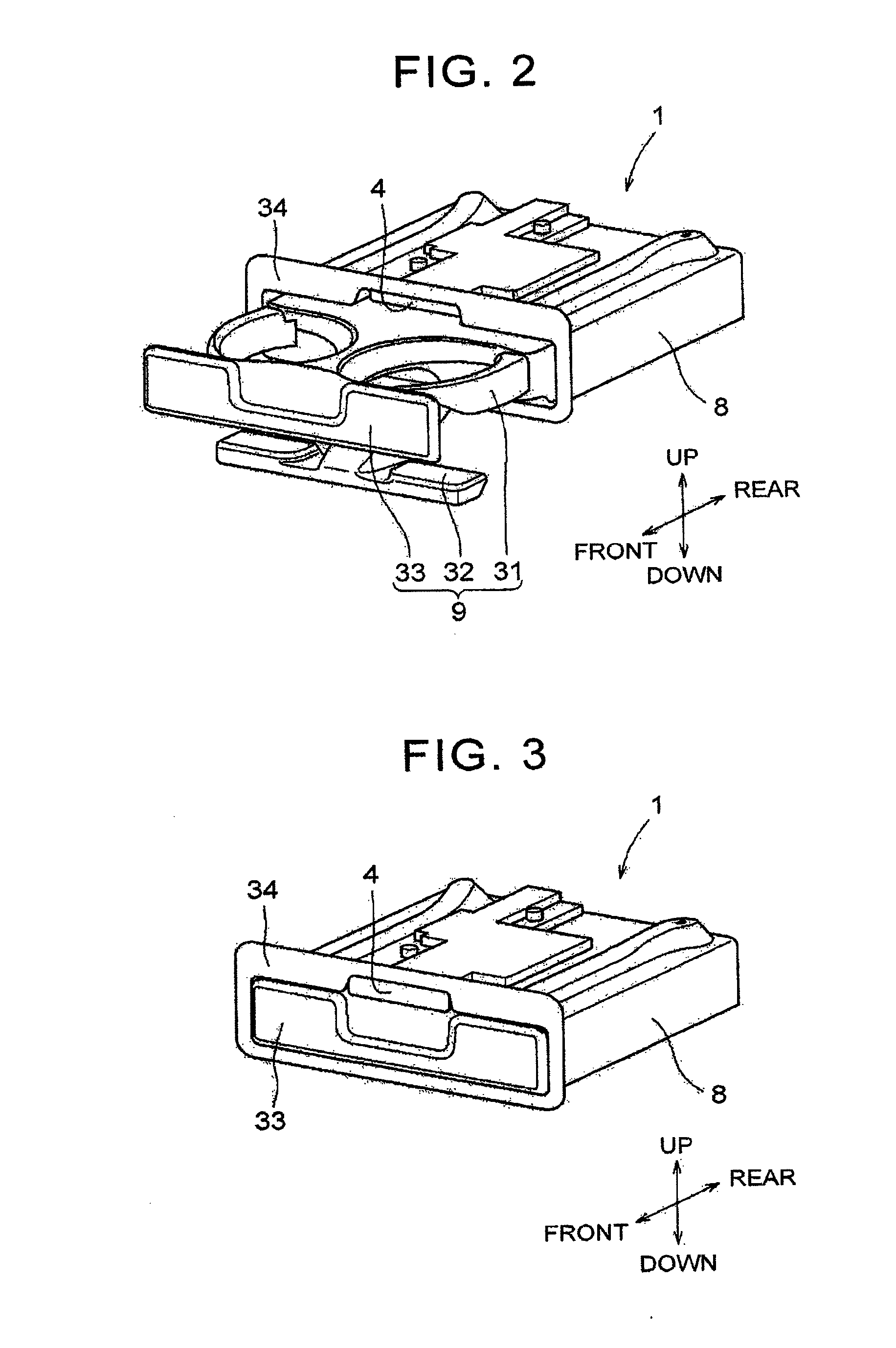
[0023]Description is hereinafter made of a mode for carrying out the present invention with reference to the drawings. The indication of directions, such as upward, downward, forward and backward, in this description is used for the convenience of description. Thus, the indication does not mean that each member should absolutely be arranged as described herein. The direction in which a storage part 3 (cup holder 9) pops out toward a use position as shown in FIG. 2 is herein defined as forward and the opposite direction, the direction in which the storage part 3 (cup holder 9) moves toward a retracted position, is defined as backward. First, the state where a storage structure 1 is adopted to a vehicle is described. FIG. 1 is a diagram that illustrates the way in which a storage structure 1 according to the present invention is incorporated in an armrest 2 at the center of a vehicle rear seat 10. The storage structure 1 is provided at an end of a rotatable armrest 2. Because the stor...


PUM


Abstract

A storage structure for a vehicle includes a storage part that is movable between a use position and a retracted position and is biased toward the use position; a lock mechanism that locks the storage part in the retracted position; and a button that is provided separately from the storage part and is used to unlock the storage part that is locked by the lock mechanism. The storage part is not moved to the use position by pressing the button from an initial position, and the storage part is moved to the use position by restoring the button from the pressed state to the initial position.

Description

INCORPORATION BY REFERENCE[0001]The disclosure of Japanese Patent Application No. 2013-003567 filed on Jan. 10, 2013 including the specification, drawings and abstract is incorporated herein by reference in its entirety.BACKGROUND OF THE INVENTION[0002]1. Field of the Invention[0003]The present invention relates to a storage structure for a vehicle. More specifically, the present invention relates to a storage structure for a vehicle which has a storage part that can be moved to a use position by pressing a button that is provided separately from the storage part.[0004]2. Description of Related Art[0005]A storage structure that is used to contain items is provided in a vehicle. A storage structure which has a storage part that can be shifted to a use state (for example, a state of being protruded forward) or a retracted state (for example, a state of being retracted backward) by pressing the storage part is known. A storage structure which has a storage part that is configured to po...

Claims


Application Information

Patent Timeline
Patent Type & Authority Applications(United States)
IPC IPC(8): B60R7/04B60N2/75
CPCB60R7/043B60N2/4613B60N2/468B60N3/102B60N2/757B60N2/79
Inventor OKUHARA, YOSHIKATSUNAGAYAMA, RYOFUJISAWA, NAOKIOGIHARA, AKIHIROMIKOSHI, HIROSHISUGIYAMA, TOSHIHIRO
Owner TOYOTA BOSHOKU KK
Why Eureka
Try Eureka