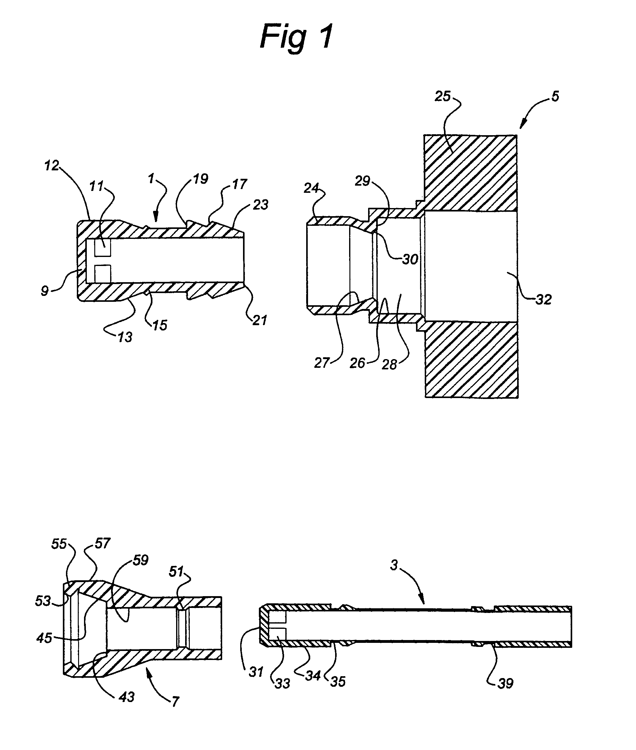
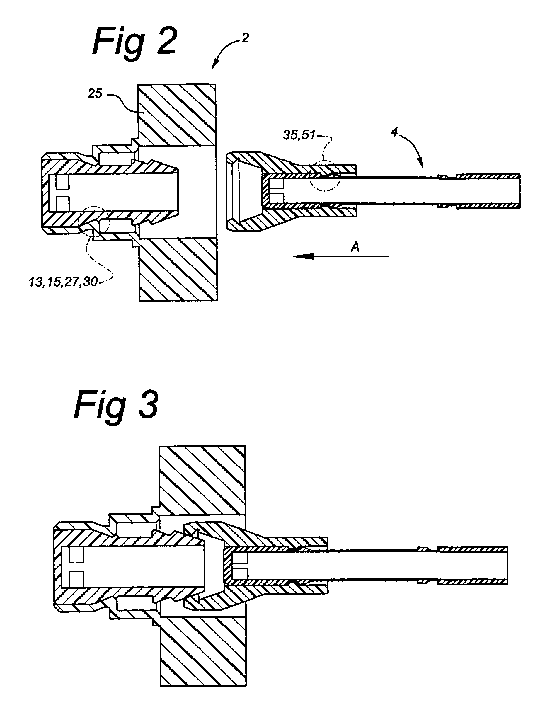
[0003]a male element which can be inserted into the female element and can be coupled thereto,an adapter socket, inside which the female element can be displaced in axial direction between a position in which it closes off the flow of medium and in which the passage openings are closed off by the adapter socket, and a position in which it allows medium to flow through and in which the passage openings are not closed off by the adapter socket, in which assembly the female element is provided, at a distance from the transverse closure wall, with connecting means which can form a connection with connecting means arranged on the male element or a coupling piece coupled to the male element, and in which assembly, as a result of actuation of the male element or said coupling piece coupled thereto, the female element can be displaced between the above-mentioned position in which it closes off the flow of medium and the above-mentioned position in which it allows medium to flow through, in which latter position the connecting means of the female element are accommodated in a relatively narrow cavity in the adapter socket, so as to form a connection to the male element or the coupling piece coupled thereto, while in the above-mentioned position in which the flow of medium is closed off, said connecting means are accommodated in a relatively wide cavity in the adapter socket, with the result that the connection between the female element and the male element or the coupling piece coupled thereto can be broken.
[0006]The object of the invention is to eliminate these drawbacks and therefore the coupling between the female element and the male element or the coupling piece coupled thereto takes place by pushing the connecting means of the female element and the connecting means of the male element or the coupling piece connected thereto on each other by which at least one of said connecting means deviates in radial direction from the neutral elastically non loaded position and returns in the radial direction into the coupling position by own elasticity.
[0007]To be able to use relatively small forces to bring about the coupling between female element and male element or coupling piece connected to the male element, the locking of the coupled connecting means of the female element and the male element or the coupling piece coupled to the male element takes place by further
axial displacement of the male element with respect to the adapter socket into a locking position spaced from the coupling position, in which locking position of the connecting means
radial displacement of the connecting means is made impossible.
[0008]Furthermore, it is preferable for the female element to be provided with means which limit the movement of the female element inside the adapter socket, and that these means as well as the connecting means of the female element are situated on the side of the passage openings which is remote from the end wall. Consequently, the movement which the female element has to make in order to open the passage openings can be relatively small. This has the
advantage that the space which is required in the packaging in order to open the passage openings remains limited. An other
advantage is that the female element can be of compact design, so that it is possible to safe on material.
[0009]It is also preferable that the assembly has blocking means on the female element and the adapter socket respectively which prevent axial movement of the female element and the adapter socket when the coupling between the female element and the male element or the coupling piece coupled to the male element is achieved, said blocking means being able to absorb an
axial load greater than the
axial load needed the couple said connecting means of the female element and the male element or the coupling piece connected thereto. This has the
advantage that less force is required for coupling: it is only necessary to bring about the coupling between the male element and the female element, why the friction caused by the sealing of the passage openings does not have to be overcome.
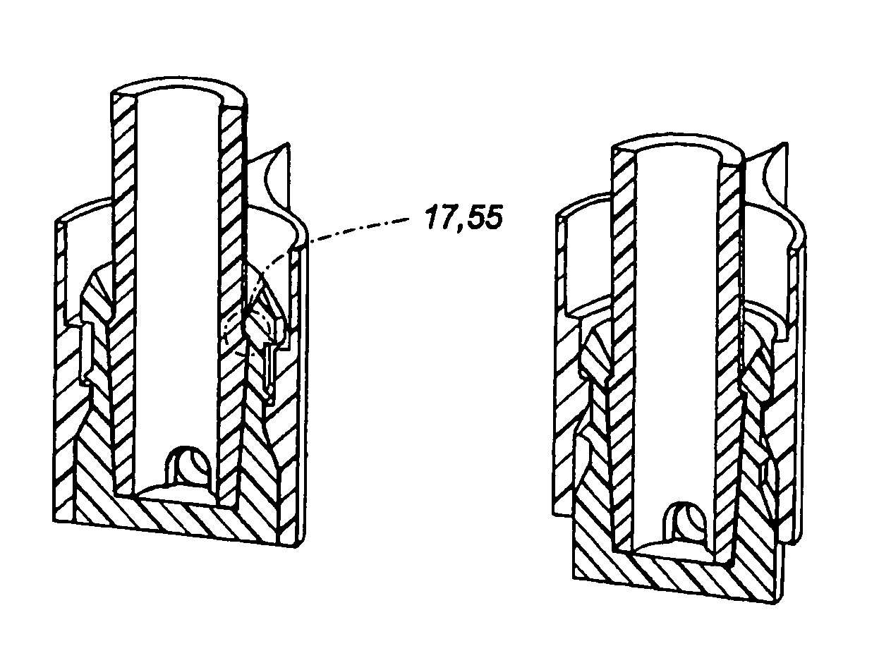
[0017]It is intended that it should be possible to produce the female element and the adapter socket in a joint operation by
injection moulding. In this case the method is characterized in that the female element and the adapter socket are produced simultaneously in line with one another, in a single mould cavity, which is formed by a number of interacting mould parts, in such a manner that, after a number of mould parts have been removed, the female element can be pulled into the adapter socket by a mould part which, during the
injection moulding, is releasably connected to the female element. Also the male element and the coupling piece could be produced in a joint operation by
injection moulding. An appropriate selection of the mould parts allows the female element to function as an injection-moulding shield for the adapter socket. This ensures that the female element and the adapter socket are moulded symmetrically, which is advantageous since it is possible to counteract undesirable deformation of the product caused by non-uniform shrinkage. Furthermore, partial seams are prevented from forming on the sealing surfaces, so that the corresponding seals have a better action and can therefore withstand higher pressures.


