
Compact hyperspectral mid-infrared spectrometer

a spectrometer and mid-infrared technology, applied in the field of spectroscopy, can solve the problems of large system, high cost of manufacture and maintenance, large system, etc., and achieve the effect of reducing the dispersion angle of wavelength signals and reducing the divergence of wavelength signals

Active Publication Date: 2022-03-29
CALIFORNIA INST OF TECH
View PDF48 Cites 2 Cited by
  • Summary
  • Abstract
  • Description
  • Claims
  • Application Information

AI Technical Summary

Benefits of technology

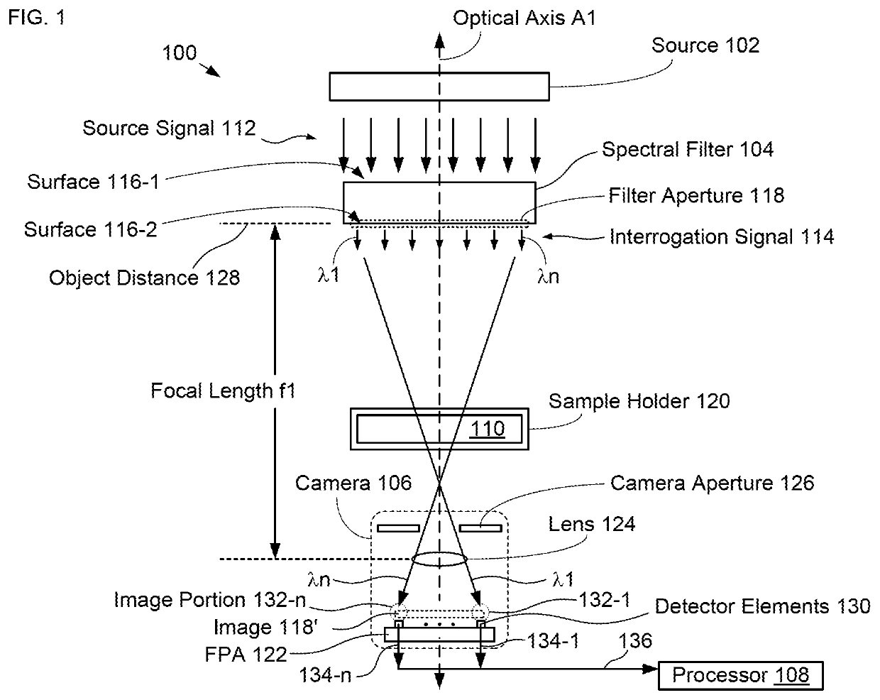
[0012]In contrast to prior-art spectrometers, embodiments in accordance with the present disclosure employ a compact thermal imaging camera comprising a focusing lens and a focal-plane array to image the filter aperture through the sample and focus an image of the filter aperture onto its focal-plane array. The resultant image includes the plurality of wavelength signals, as impacted by absorption in the sample, and each wavelength signal is detected at a different detector element of the focal-plane array. By imaging the filter aperture through the sample using a compact thermal imager, spectrometers in accordance with the present disclosure can be more compact and lower cost than prior-art spectrometers. In addition, by locating the filter aperture such that its image is focus at the detector elements, the divergence of the light in the interrogation signal is reduced, thereby reducing the spectral range that surrounds the center wavelength of each wavelength signal. Furthermore, the readout rate of the infrared imaging camera is fast enough to enable spectral acquisition times of one second or less.
[0017]In some embodiments, the spectral filter is configured to reduce the dispersion angle of the wavelength signals in the source signal as it provides the interrogation signal; therefore, at least some of the wavelength signals received at the detector elements include a narrower range of wavelengths that surround their center wavelength. Furthermore, the divergence of the wavelength signals is also reduced by the fact that the spectral filter is positioned such that its image is in focus on the detector arrays.

Problems solved by technology

Unfortunately, FTIR spectrometry requires large, highly complex interferometers having long optical paths and optical components, such as mirrors and beam splitters, whose alignment must be precisely maintained.
As a result, such systems are large, complex, and expensive to manufacture and maintain over their lifetime.
Although there have been attempts to miniaturize FTIR spectroscopy systems for operation in the MIR spectral range, such systems still require the fabrication and alignment of a number of precisely controlled structures.
As a result, prior-art miniaturized FTIR spectroscopy systems are not well suited for use in many applications, such as point of care health monitoring, pollution investigation and pharmaceutical testing.
Furthermore, operation in the MIR spectral range gives rise to additional challenges due to the fact that the set of materials suitable for use in optical components operable at MIR wavelengths is limited and such materials are often prohibitively expensive.
As a result, to date, conventional infrared spectrometers for operation in the MIR spectral range remain quite large and complex and, typically, suffer from narrow bandwidth or wavelength resolution that is too coarse to effectively identify many chemicals and compounds.
The need for a small, low-cost spectrometer capable of performing a high-quality chemical and / or molecular analysis of a sample remains, as yet, unmet in the prior art.
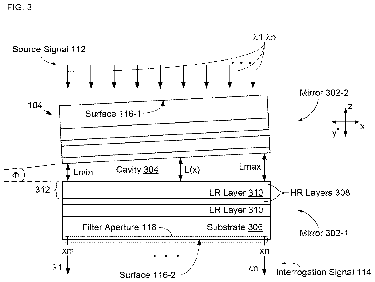
In addition, the spectral filter is configured such that the spectral range of the interrogation signal is limited such that only one wavelength signal is passed at each location along the first axis.

Method used


Image

  • Compact hyperspectral mid-infrared spectrometer
  • Compact hyperspectral mid-infrared spectrometer
  • Compact hyperspectral mid-infrared spectrometer

Examples


Embodiment Construction

[0032]FIG. 1 depicts a schematic drawing of schematic drawing of an illustrative embodiment of an MIR spectrometer in accordance with the present disclosure. Spectrometer 100 includes source 102, spectral filter 104, camera 106, and processor 108, where source 102, spectral filter 104, and camera 106 are aligned along optical axis A1, which passes through sample 110.

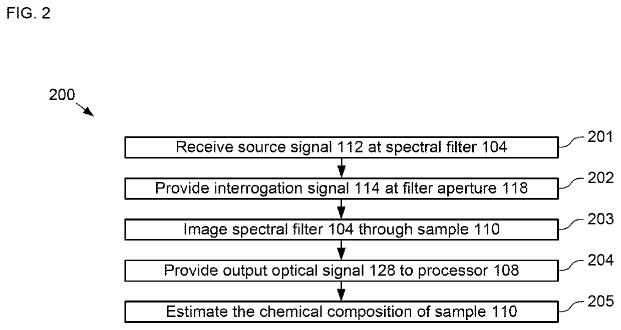
[0033]FIG. 2 depicts operations of a method for performing MIR spectroscopy in accordance with the illustrative embodiment. Method 200 is described herein with continuing reference to FIG. 1, as well as reference to FIGS. 3-4A-B. Method 200 begins with operation 201, wherein spectral filter 104 receives source signal 112 from source 102.

[0034]Source 102 is a conventional broadband blackbody light source that provides source signal 112. In the depicted example, source signal 112 is has a continuous spectral range having spectral width, SR1, which extends from λmin to λmax with center wavelength λc1. In the depicted exampl...


PUM

PropertyMeasurementUnit
wavelength rangeaaaaaaaaaa
lengthaaaaaaaaaa
incident angleaaaaaaaaaa

Abstract

An infrared spectrometer for operation in the mid-infrared spectral range is presented, where the spectrometer includes a Bragg-mirror-based spectral filter that is operative for providing an interrogation signal whose spectral content is dispersed along a first direction at a filter aperture. The filter aperture is imaged through a sample by a thermal-imaging camera to create a focused image that is based on the interrogation signal and the absorption characteristics of the sample. As a result, embodiments in accordance with the present disclosure can be smaller, less complex, and less expensive than infrared spectrometers known in the prior art.

Description

RELATED APPLICATIONS[0001]This application claims the benefit of U.S. Provisional Application No. 62 / 801,762 filed Feb. 6, 2019, which is incorporated herein by reference. If there are any contradictions or inconsistencies in language between this application and one or more of the cases that have been incorporated by reference that might affect the interpretation of the claims in this case, the claims in this case should be interpreted to be consistent with the language in this case.FIELD OF THE INVENTION[0002]The present invention relates to spectroscopy in general and, more particularly, to hyperspectral spectrometers for use in the mid-infrared spectrum.BACKGROUND OF THE INVENTION[0003]Infrared spectroscopy enables analysis of the chemical composition of a sample by interrogating the material with light (or, alternatively, radiation) within a spectral range and determining the absorption spectrum of the sample material. Infrared spectroscopy is widely used in many applications, ...

Claims


Application Information

Patent Timeline
Patent Type & Authority Patents(United States)
IPC IPC(8): G01J3/28H04N5/33G01J3/02
CPCG01J3/2823G01J3/0208G01J3/0291H04N5/33G01J2003/2826G01J2003/1234G01J3/26G01J3/42
Inventor SCHERER, AXELJEON, TAEYOON
Owner CALIFORNIA INST OF TECH
Learn More