
Film thickness measuring apparatus and film thickness measuring method

a film thickness and measuring method technology, applied in the direction of optical radiation measurement, instruments, spectrometry/spectrophotometry/monochromators, etc., can solve the problems of inability to obtain an accurate reflectance, increased tact time, and possible measurement target objects

Active Publication Date: 2022-04-05
OTSUKA DENSHI CO LTD
View PDF10 Cites 0 Cited by
  • Summary
  • Abstract
  • Description
  • Claims
  • Application Information

AI Technical Summary

Benefits of technology

[0007]The present invention has been made to solve the above-described problem, and an object thereof is to provide a film thickness measuring apparatus and a film thickness measuring method that can measure a film thickens in a shorter period of time, while preventing the measurement target object from being contaminated when measuring the film thickness.

Problems solved by technology

Due to such fluctuations, there is a problem in that it is not possible to obtain an accurate reflectance.
With the techniques according to Patent Document 1 and Patent Document 2 described above, for example, the tact time is increased due to the process of moving the setting platform for the measurement target object, and also a problem such as contamination or the like of the measurement target object may occur due to a movable mirror being operated above the measurement target object.

Method used


Image

  • Film thickness measuring apparatus and film thickness measuring method
  • Film thickness measuring apparatus and film thickness measuring method
  • Film thickness measuring apparatus and film thickness measuring method

Examples


Embodiment Construction

Film Thickness Measuring Apparatus

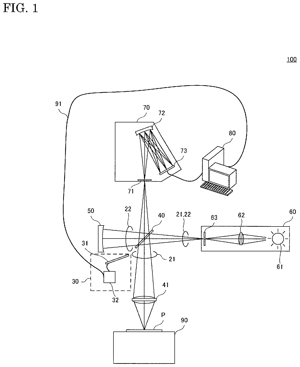
[0034]FIG. 1 is a diagram showing an example of a configuration of a film thickness measuring apparatus according to an embodiment of the present invention.

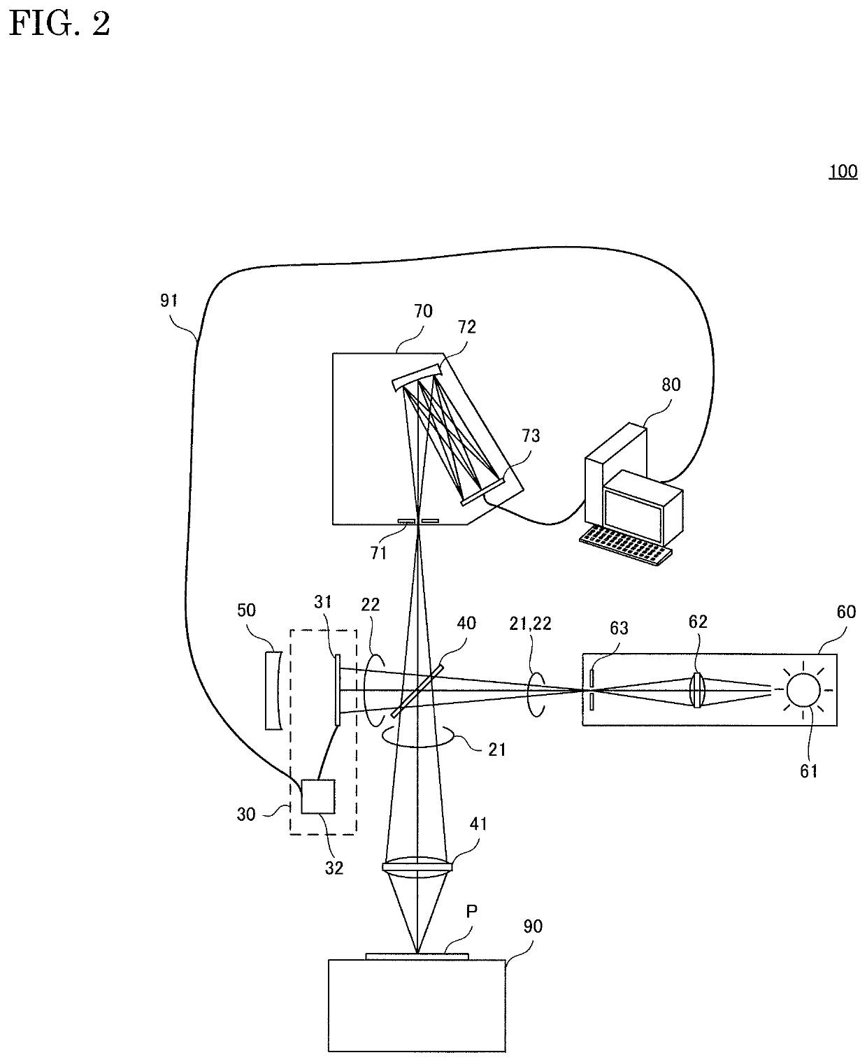
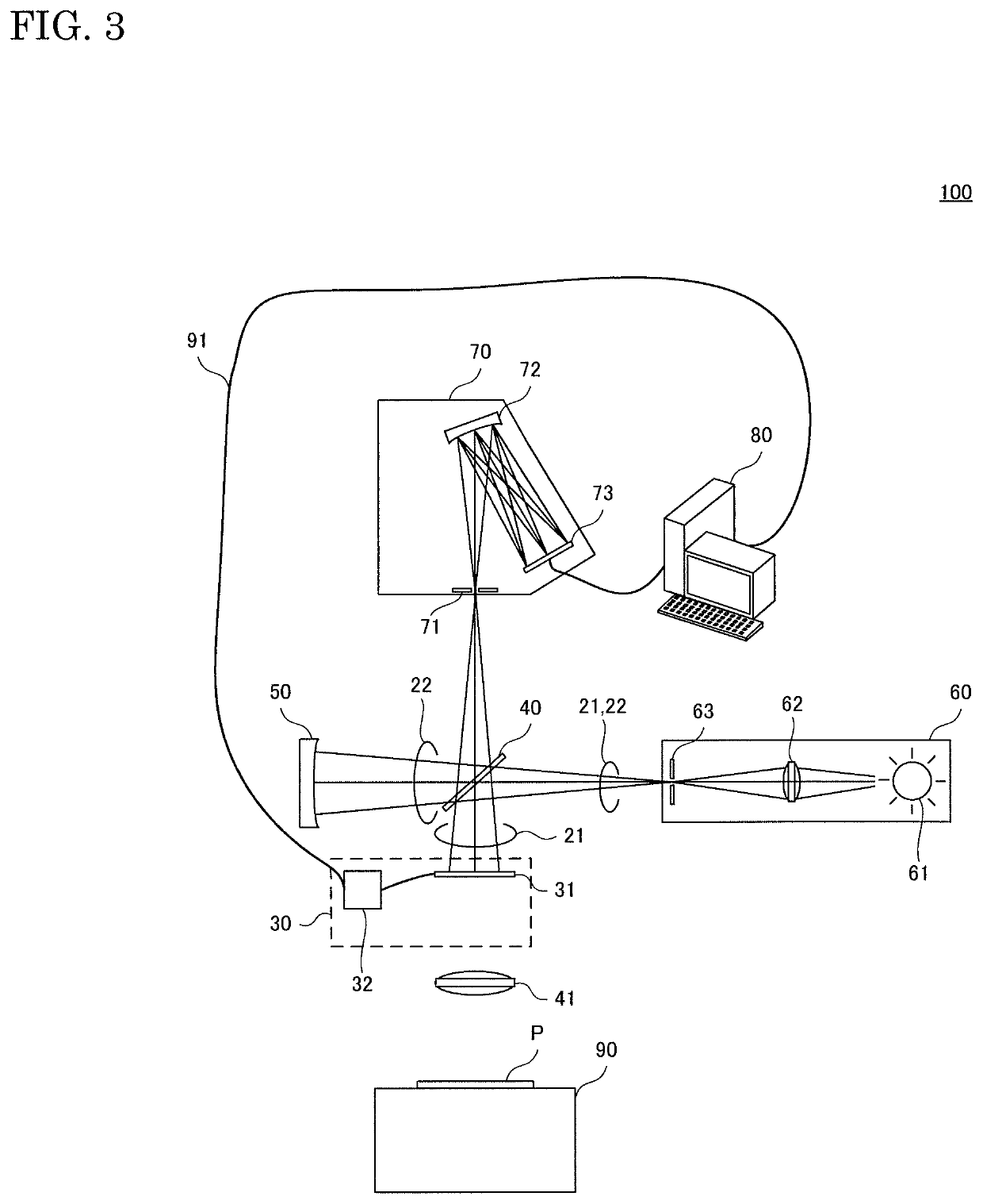
[0035]As shown in FIG. 1, a film thickness measuring apparatus 100 includes a measurement light path 21, a correction light path 22, and a light switching unit 30.

[0036]For example, the film thickness measuring apparatus 100 also includes a beam splitter 40, a light condensing lens 41, a reference member 50, a light source 60, a spectroscope 70, a processing device 80, and a sample platform 90.

[0037]A target object P is to be placed on the sample platform 90. More specifically, a measurement target object S or a reflection plate R is to be placed on the sample platform 90 as the target object P. The reflection plate R may be an aluminum mirror, a glass plate, or an Si plate, for example. The film thickness measuring apparatus 100 is an apparatus for measuring the film thickness of the measurement...


PUM

PropertyMeasurementUnit
timeaaaaaaaaaa
thicknessaaaaaaaaaa
spectrumaaaaaaaaaa

Abstract

A film thickness measuring apparatus including: a measurement light path for irradiating a measurement target object with light from a light source; a correction light path for irradiating a reference member with light from the light source; and a light switching unit that selectively guides reflected light from the measurement target object or reflected light from the reference member, to a spectroscope.

Description

CROSS-REFERENCE TO RELATED APPLICATION[0001]This application is based upon and claims the benefit of priority from Japanese patent application No. 2019-203869, filed on Nov. 11, 2019, the disclosure of which is incorporated herein in its entirety by reference.BACKGROUND OF THE INVENTIONField of the Invention[0002]The present invention relates to a film thickness measuring apparatus and a film thickness measuring method.Description of Related Art[0003]There is a known conventional technique for irradiating a measurement target object and a reference member with light and measuring the film thickness of the measurement target object based on reflected light from the measurement target object and reflected light from the reference member. However, irradiation light with which the measurement target object and the reference member are irradiated, reflected light from the measurement target object, and reflected light from the reference member fluctuates over time due to temporal changes...

Claims


Application Information

Patent Timeline
Patent Type & Authority Patents(United States)
IPC IPC(8): G01B11/06G01N21/25
CPCG01B11/0625G01N21/255G01B21/042G01B11/0616G01N21/314G01J3/06G01J2003/065
Inventor KAWAGUCHI, SHIRONAKAJIMA, KAZUYA
Owner OTSUKA DENSHI CO LTD
Learn More