
Method for forming a laminate

a technology of laminates and forming methods, applied in the direction of process and machine control, mechanical control devices, instruments, etc., can solve the problems of high waste generation, high cost of production, and high time requirements, and achieve the effect of increasing the amount of si, direct measurement, and short tim

Active Publication Date: 2012-04-03
MEC CO LTD
View PDF15 Cites 0 Cited by
  • Summary
  • Abstract
  • Description
  • Claims
  • Application Information

AI Technical Summary

Benefits of technology

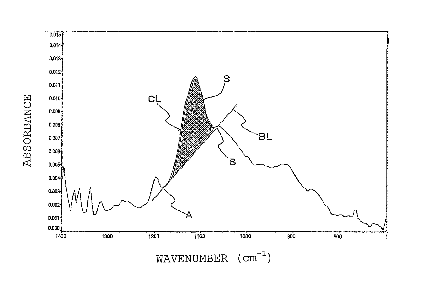
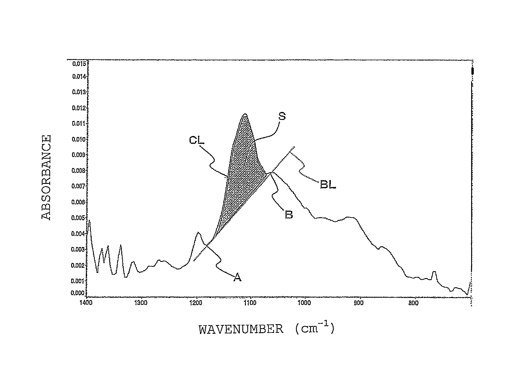
The present invention provides a method for forming a laminate that can maintain the adhesive performance of silane coupling agent coatings on a resin layer even when the treatment step is continuously conducted, while also decreasing production costs. The method involves applying an aqueous solution of silane coupling agent onto a metal layer and drying it to form a coating, followed by laminating a resin layer onto the coating. The amount of silicon in the coating surface can be measured using FT-IR with a reflection absorption spectrometry, which allows for the renewal or increase of the silane coupling agent solution to maintain adhesive performance. This method also prevents the need for unnecessary solution exchange and reduces production costs.

Problems solved by technology

As a result, much waste is generated against economy and work efficiency.
Thus, costs for the production are not easily decreased.
However, according to the measurement based on XPS, for example, the following problems are caused: (1) The measurement needs to be made under a vacuum condition; thus, much time is required therefor.
(2) A machine therefor is expensive.
Thus, the measurement is not easily made, in particular, in order to control silane coupling agent coatings when wiring boards are mass-produced.

Method used


Image

  • Method for forming a laminate
  • Method for forming a laminate

Examples


example 1

Preparation of an Aqueous Silane Coupling Agent Solution

[0040]2-(3,4-Epoxycyclohexyl)ethyltrimethoxysilane (silane coupling agent) was dissolved in ion exchange water to yield an aqueous silane coupling agent solution (concentration: 1.0% by weight) to be used in Example 1.

[0041](Formation of a Silane Coupling Agent Coating)

[0042]As a test substrate, prepared was an electrolytic copper foil piece (product name: 3EC-III, manufactured by Mitsui Mining & Smelting Co., Ltd., thickness: 35 μm) cut into a size of 100 mm×100 mm. This was immersed in a 10% by weight sulfuric acid solution for 30 seconds to clean the copper foil piece surfaces. The test substrate was then rinsed with water and dried. Next, this test substrate was subjected to immersion swinging treatment (at 30° C. for 30 seconds) with a substituting tin-plating solution (T-9900) manufactured by Mec Co., Ltd., and then rinsed with water to form a tin-plating treatment layer on each surface of the copper foil piece. Just ther...

example 2

[0045]An evaluation was made in the same way as in Example 1 except that: a measurement was neither made just after the preparation nor after 30 to 90 minutes from the stirring; without making the complete exchange after the continuous use for 4 weeks, the temperature and the time for pre-drying the applied film were changed to “80° C. and 40 seconds”, respectively; and afterwards, the continuous use under the pre-drying conditions (temperature and time) was performed. The results are shown in Table 1.

example 3

[0046]An evaluation was made in the same way as in Example 1 except that: a measurement was neither made just after the preparation nor after 30 to 90 minutes from the stirring; without making the complete exchange after the continuous use for 4 weeks, the temperature and the time for pre-drying the applied film were changed to “80° C. and 20 seconds”, respectively; and afterwards, the continuous use under the pre-drying conditions (temperature and time) was performed. The results are shown in Table 1.


PUM

PropertyMeasurementUnit
wavenumberaaaaaaaaaa
atmospheric temperatureaaaaaaaaaa

Abstract

The method for forming a laminate of the present invention is a method for forming a laminate, comprising a silane coupling agent treatment step of applying an aqueous solution of a silane coupling agent onto a surface of a metal layer, and drying the resultant applied film to form a silane coupling agent coating, and a lamination step of laminating a resin layer on the silane coupling agent coating, these steps being continuously performed, wherein when the formed silane coupling agent coating is analyzed in the silane coupling agent treatment step by FT-IR with a reflection absorption spectrometry and then the peak area of Si—O is turned to a value less than a predetermined threshold value, at least one part of the aqueous solution of the silane coupling agent is renewed, thereby conducting the silane coupling agent treatment while the peak area is controlled into a predetermined range.

Description

BACKGROUND OF THE INVENTION[0001]1. Field of the Invention[0002]The present invention relates to a method for forming a laminate, wherein the following steps are continuously conducted: a silane coupling agent treatment step of applying an aqueous solution of a silane coupling agent onto a surface of a metal layer, and drying the resultant applied film to form a silane coupling agent coating; and a lamination step of laminating a resin layer on the silane coupling agent coating.[0003]2. Description of Related Art[0004]Hitherto, in the production of a printed wiring board, the following step is generally conducted in order to improve adhesive performance between a surface of a conductor made of a metal such as copper or copper alloy (metal surface) and an insulating resin of a solder resist, a prepreg or the like: the step of applying an aqueous solution of a silane coupling agent, or the like onto the metal surface, and then drying the resultant applied film (see, for example, Japan...

Claims


Application Information

Patent Timeline
Patent Type & Authority Patents(United States)
IPC IPC(8): B32B41/00
CPCB32B37/203H05K3/389B32B38/0012B32B2037/243B32B2038/168B32B2309/02B32B2309/04H05K2203/163H05K1/0269H05K3/022H05K2201/0355H05K2203/1476B32B2457/00
Inventor KAWAGUCHI, MUTSUYUKIAMATANI, TSUYOSHI
Owner MEC CO LTD
Learn More