Adjustable laser leveling device with distance measuring lasers and self-leveling lasers and related method

a laser leveling device and laser leveling technology, applied in the direction of distance measurement, reference lines/planes/sectors, instruments, etc., can solve the problem that the tool is generally limited to providing reference laser lines

Active Publication Date: 2022-04-12
SURE HANG LLC
View PDF25 Cites 0 Cited by
  • Summary
  • Abstract
  • Description
  • Claims
  • Application Information

AI Technical Summary

Benefits of technology

[0007]The inclusion of distance measuring lasers allows the user to measure distances from the center of a base placed over a datum point without using a tape measure or other distance measuring tool.
[0011]The present invention advantageously allows level visible laser lines to be established, broadcast, and projected onto a wall or other work surface while the user makes multiple layout marks. More particularly, the present invention facilitates leveling and arrangement of objects on a wall or other work surface by allowing the user to easily measure distances from a datum point to additional points in the layout, along level, visible laser lines projected onto the work surface. Additional bases may be placed over other reference points on the work surface, which reference points originate from the initial datum point. The use of more than one base in any layout allows the laser assembly to be moved from base to base effectively and efficiently within said layout field without interrupting previously identified marks in the layout.
[0012]An alternative embodiment of the present invention is a laser leveling device with a base that is capable of being removably affixed to a wall or other work surface and one or more distance measuring lasers rotatably mounted to said the base, wherein the user is able to rotatably adjust the distance measuring lasers to orient the lasers to a desired position for measuring distances in various directions and at various angles from the center of the base.
[0013]A further alternative embodiment of the present invention is a laser assembly with one or more lasers where the laser assembly is rotatably and removably attached to a base, wherein the user is able to rotatably adjust the laser assembly on said base to orient the lasers in the laser assembly to a desired position.

Problems solved by technology

However, such tools are generally limited to providing reference laser lines and require the user to move the tool and interrupt the reference lines in order to complete complex layouts.

Method used


Image

  • Adjustable laser leveling device with distance measuring lasers and self-leveling lasers and related method
  • Adjustable laser leveling device with distance measuring lasers and self-leveling lasers and related method
  • Adjustable laser leveling device with distance measuring lasers and self-leveling lasers and related method

Examples


Embodiment Construction

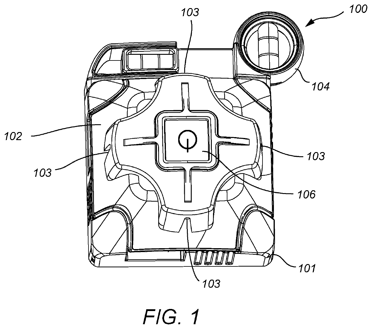
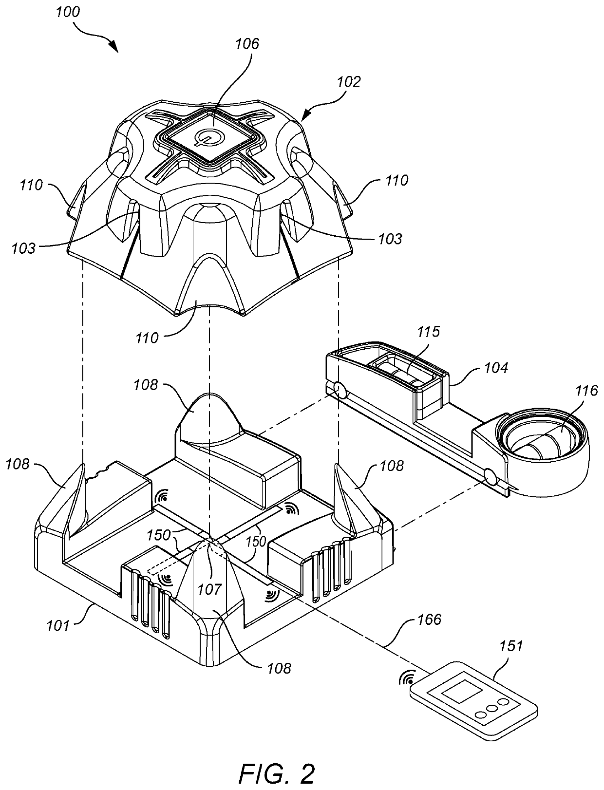
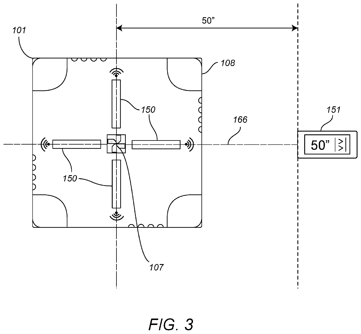
[0027]The present invention is best understood by reference to the drawings and description set forth herein. Embodiments of the invention are discussed below with reference to the drawings. However, those skilled in the art will readily appreciate that the detailed description given herein with respect to the drawings is for explanatory purposes as the invention extends beyond the limited embodiments described. For example, in light of the teachings of the present invention, those skilled in the art will recognize a multitude of alternate and suitable approaches, depending upon the needs of the particular application, to implement the functionality of any given detail described herein beyond the particular implementation choices in the following embodiments described and shown. Numerous modifications and variations of the invention exist, which are too numerous to be listed but that all fit within the scope of the invention. Also, singular words should be read as plural and vice ve...


PUM

PropertyMeasurementUnit
anglesaaaaaaaaaa
distanceaaaaaaaaaa
fir distanceaaaaaaaaaa

Abstract

A device and method for projecting visible level laser lines onto a work surface and measuring distances along the level laser lines. The device includes a self-leveling laser housing that allows the lasers to level when activated. The device also includes separate distance measuring lasers and a handheld display used to measure distances from the center of the device.

Description

[0001]This is the United States National Stage of Patent Cooperation Treaty Application No. PCT / US2016 / 041295 filed Jul. 7, 2016, the disclosures of which are incorporated herein by reference in their entireties.FIELD OF INVENTION[0002]The present invention relates to a laser leveling device as generally described in U.S. Pat. No. 9,518,823, and specifically to certain improvements for the laser leveling device, namely: the use of distance measuring lasers and a self-leveling laser housing in the laser leveling device.BACKGROUND[0003]There are various tools on the market that utilize line lasers. However, such tools are generally limited to providing reference laser lines and require the user to move the tool and interrupt the reference lines in order to complete complex layouts. What is needed is a device to facilitate leveling and installation of objects and fixtures, such as shelving, home décor, cabinets, and tile, without moving or interrupting the device continuously. Further ...

Claims


Application Information

Patent Timeline
Patent Type & Authority Patents(United States)
IPC IPC(8): G01C15/00G01B11/14G01B11/02
CPCG01C15/004G01B11/02G01B11/14G01C15/002G01C3/08
Inventor HILL, JAYSON
Owner SURE HANG LLC
Why Eureka
Try Eureka