Data processing device of production equipment

a technology of production equipment and data processing, which is applied in the direction of program control, testing/monitoring control system, instruments, etc., can solve the problems of harm in using data on a real-time basis, and achieve the effect of easy generation and grasping the state of production equipmen

Active Publication Date: 2022-04-12
JTEKT CORP
View PDF36 Cites 0 Cited by
  • Summary
  • Abstract
  • Description
  • Claims
  • Application Information

AI Technical Summary

Benefits of technology

[0012]A first object of the present invention is to provide a data processing device of production equipment that can generate data usable by an operator or an administrator by performing processing for a collected plurality of types of data.
[0013]It is requested to appropriately detect a state of production equipment and suitably utilize a result of the detection of the state of the production equipment. A second object of the present invention is to provide a data processing device of production equipment that can appropriately detect a state of the production equipment and suitably utilize a result of the detection of the state of the production equipment.
[0016]A third object of the present invention is to provide a tool life predicting device capable of performing life prediction for a tool in production of a variety of products in small amounts and capable of performing highly accurate life prediction for the tool by considering a state of the tool from a start of use until exhaustion of life of the tool.
[0017]To solve the first problem, a data processing device of production equipment according to the present invention is configured as follows. The data processing device of the production equipment includes: a reference-data acquiring unit configured to acquire, in the production equipment, reference data including information concerning time in which a reference for grouping of data operates; a target-data acquiring unit configured to acquire target data concerning a state of the production equipment detected by a detector provided in the production equipment; and a combined-data generating unit configured to generate, for each group of the reference data, combined data for each group obtained by combining, with the reference data, data detected in a same period of time as an operation period of time of the reference data in the target data.

Problems solved by technology

This has a harmful effect in using data on a real-time basis.

Method used


Image

  • Data processing device of production equipment
  • Data processing device of production equipment
  • Data processing device of production equipment

Examples


first embodiment

1. First Embodiment

(1-1. Configuration of Production Equipment 1)

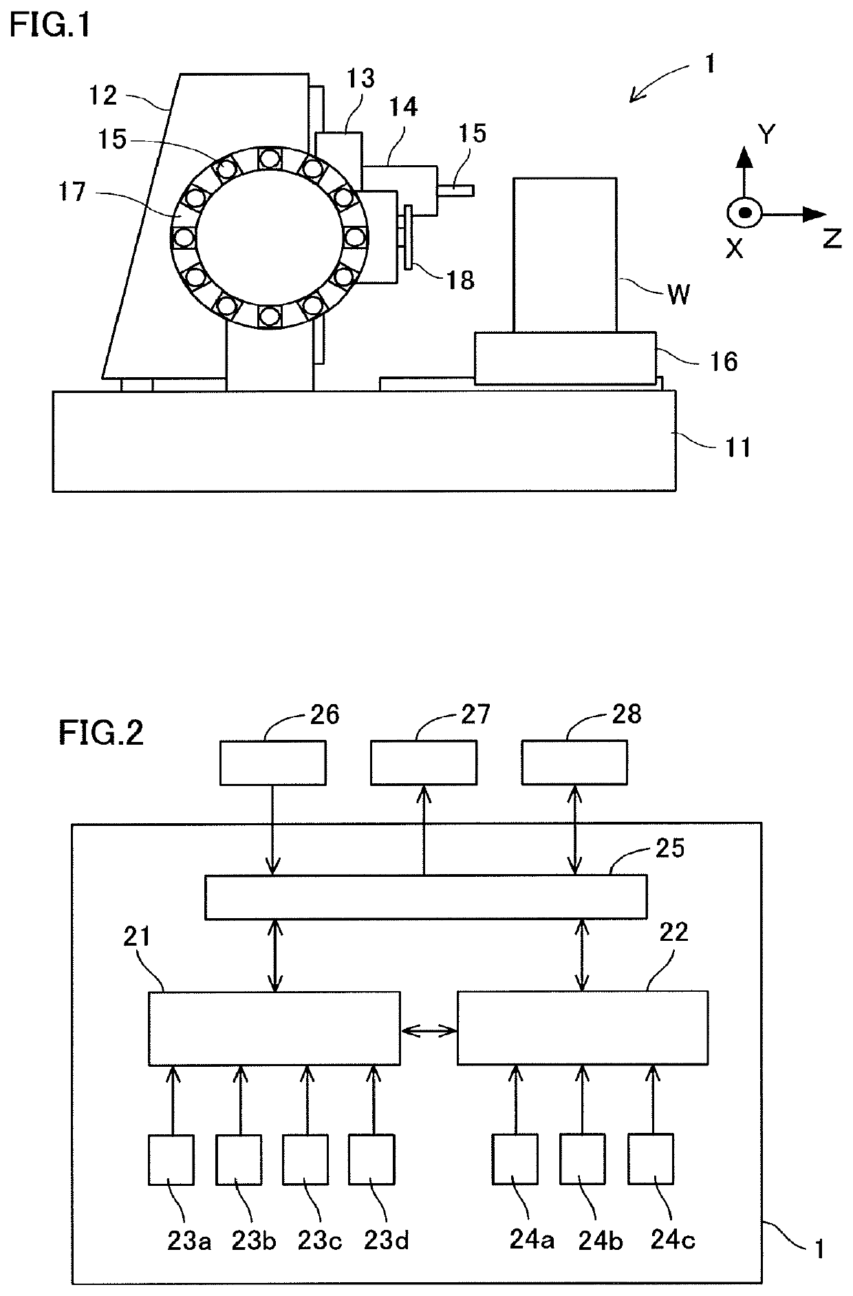
[0066]Production equipment 1 is equipment that produces a predetermined production target object W. The production equipment 1 includes various types of equipment such as a machine tool, an injection molding machine, a casting machine, a conveying device, and an industrial robot. For example, in the machine tool, the production target object W is a workpiece, which is a machining target.

[0067]An example of the production equipment 1 is explained with reference to FIGS. 1 and 2. The production equipment is a machine tool that machines a workpiece in a production line. A lateral machining center is explained as an example. Note that, as the configuration of the machining center functioning as the production equipment 1, various publicly-known configurations can be adopted besides a configuration explained below.

[0068]The machining center is configured, for example, as explained below. A bed 11 is fixed to a setting surfa...

second embodiment

2. Second Embodiment

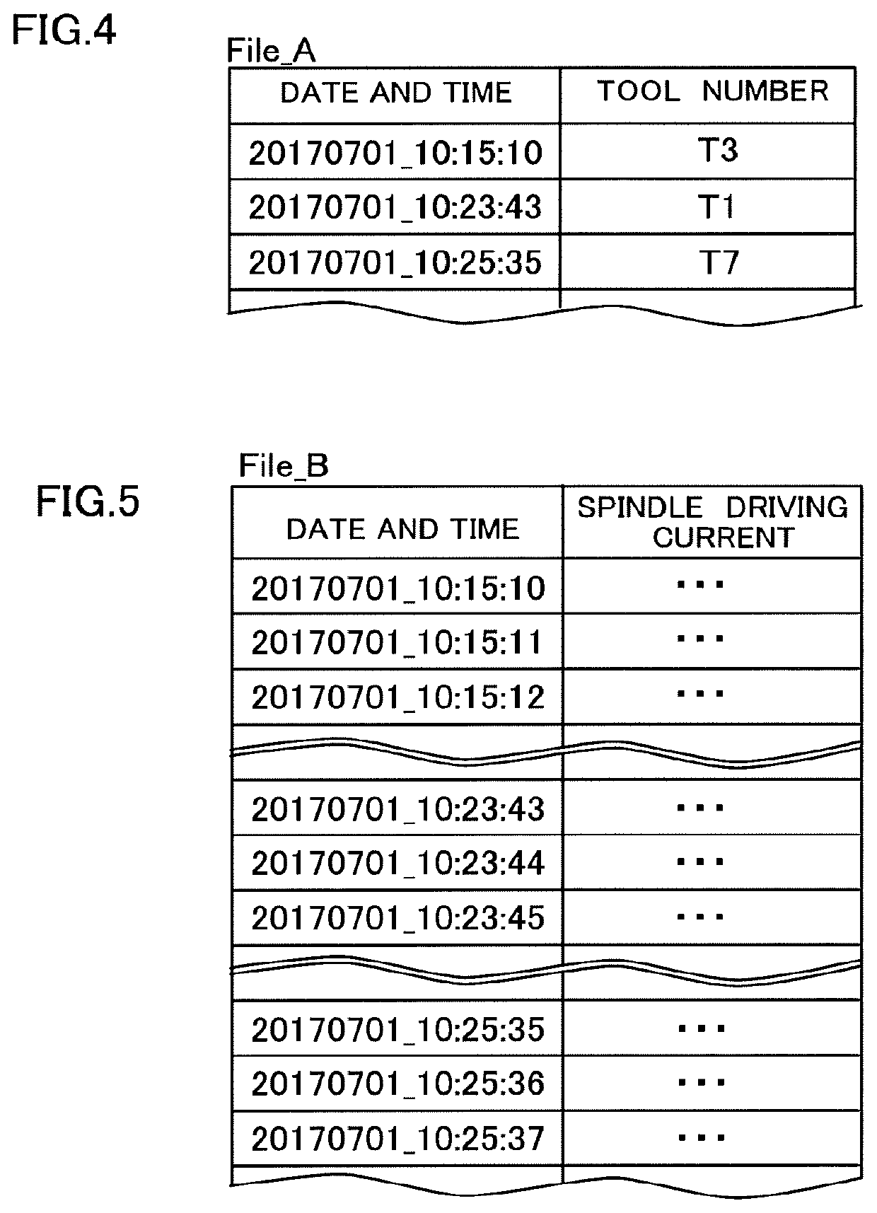
[0102]In the first embodiment, the reference data is the data concerning the tool number, which is the identification information, of the tool 15 in use among the plurality of tools 15. That is, the group is a group corresponding to each of the plurality of tools 15.

[0103]Besides, for example, as shown in FIG. 8, the reference data (File_A2) can be data concerning identification information for a machining process being executed among a plurality of machining processes (a process A, a process B, and a process C). That is, the reference data (File_A2) includes time (date and time) when a machining process, which is a reference for grouping, operates and identification information of a machining process executed at the time. In this case, the group is a group corresponding to each of the plurality of machining processes.

[0104]The machining processes mean processes such as boring rough machining, boring finish machining, milling rough machining, milling finish machi...

third embodiment

3. Third Embodiment

[0105]An injection molding machine is explained as an example of production equipment 50 with reference to FIGS. 9 to 10. The injection molding machine molds a product having a desired shape by injecting resin, which is a molding material, into a mold.

[0106]The injection molding machine includes a bed 51 set on a setting surface, a moving clamp 52 movably provided on the bed 51, a moving mold 53 detachably attached to the moving clamp 52, and a moving motor 54 that moves the moving clamp 52 with respect to the bed 51.

[0107]Further, the injection molding machine includes a fixed clamp 55 fixed on the bed 51, a fixed mold 56 detachably attachable to the fixed clamp 55, motors for mold closing 57a and 57b for giving a mold closing force to the fixed mold 56, and a plurality of injection plungers 58 and 59 for injecting the molding material to the fixed mold 56. Note that two injection plungers 58 and 59 are provided in this embodiment. However, three or more injectio...


PUM


Abstract

To provide a data processing device of production equipment that can generate data usable by an operator or an administrator by performing processing for a collected plurality of types of data. A data processing device includes a reference-data acquiring unit configured to acquire, in production equipment, reference data including information concerning time in which a reference for grouping of data operates, a target-data acquiring unit configured to acquire target data concerning a state of the production equipment detected by detectors provided in the production equipment, and a combined-data generating unit configured to generate, for each group of the reference data, combined data for each group obtained by combining, with the reference data, data detected in the same period of time as an operation period of time of the reference data in the target data.

Description

CROSS REFERENCE TO RELATED APPLICATIONS[0001]This application claims priority based on Japanese Patent Application No. 2017-156262 filed on Aug. 11, 2017, Japanese Patent Application No. 2017-156263 filed on Aug. 11, 2017, and Japanese Patent Application No. 2017-209547 filed on Oct. 30, 2017, the entire contents of which are incorporated by reference herein.BACKGROUND OF THE INVENTIONTechnical Field[0002]The present invention relates to a data processing device of production equipment.Background Art[0003]JP-A-2016-224938 describes an abnormality diagnosis system for detecting, with a microphone or a vibration sensor, abnormality of drive components in a monitoring target device including a plurality of driving units. The abnormality diagnosis system separates sensor signals detected by the sensor for each of the drive components of different types and for each of the drive components of the same types having different operation timings and performs abnormality discrimination using ...

Claims


Application Information

Patent Timeline
Patent Type & Authority Patents(United States)
IPC IPC(8): G05B23/02G05B19/4065
CPCG05B23/0205G05B19/4065G05B23/0221G06F2119/04G06F30/17G06F30/20
Inventor KATO, TOMOHISAUCHINO, AKIOYOTSUI, TOSHIHIKOISHIGURE, YUKIHARA, ASAMIKUNDOZEROVA, TATIANAOSHIUMI, TATSUO
Owner JTEKT CORP
Why Eureka
Try Eureka