
Methods and apparatuses for transmitting and receiving a preemption indication

a preemption indication and apparatus technology, applied in the field of wireless communication techniques, can solve the problems of unpredictability of urccls, large payload of gc-dci, unnecessary indication, etc., and achieve the effect of efficient preemption indication, low overhead, and monitoring of preemption indications

Active Publication Date: 2022-04-12
NEC CORP
View PDF8 Cites 0 Cited by
  • Summary
  • Abstract
  • Description
  • Claims
  • Application Information

AI Technical Summary

Benefits of technology

This approach significantly reduces the overhead of preemption indications, providing a more efficient solution by leveraging slot structure information and preconfiguring frequency regions, thus enhancing the accuracy and efficiency of resource preemption notifications in wireless communication systems.

Problems solved by technology

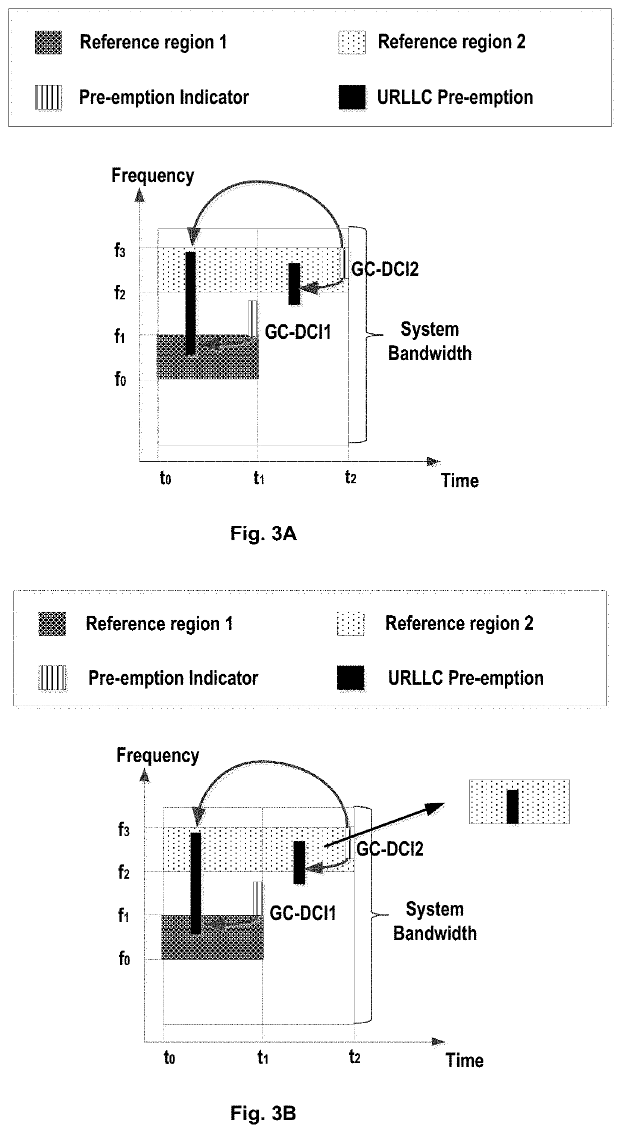
However, it might require a rather large payload of GC-DCI, and the URCCLs are un-predictable since it is hard to know how many URLLCs will occur.
Moreover, this solution also is involved in an issue on unnecessary indication.
However, due to the un-predictability, it is required to further indicate the number of GC-DCIs, which means an extra signaling overhead.
In addition, UE needs to monitor all the GC-DCIs since it does not know whether to monitor GC-DCI or which GC-DCI to monitor.
Thus, the UE might make substantial blind-decoding attempts.
Moreover, issues on the repeated indication and unnecessary indication still exist in this option.
In addition, it is also hard to decide the size of GC-DCI2 and the overhead might be very large due to the unpredictability of the URLLC.
At the same time, the solution also has issues on repeated indication and unnecessary indication.
However, there are still similar issues to those two possible options as mentioned above.
However, these current solutions cannot meet requirements of efficient preemption indications and thus there is a need for improved preemption indication solution in the art.

Method used


Image

  • Methods and apparatuses for transmitting and receiving a preemption indication
  • Methods and apparatuses for transmitting and receiving a preemption indication
  • Methods and apparatuses for transmitting and receiving a preemption indication

Examples


Embodiment Construction

[0050]Hereinafter, the solution as provided in the present disclosure will be described in details through embodiments with reference to the accompanying drawings. It should be appreciated that these embodiments are presented only to enable those skilled in the art to better understand and implement the present disclosure, not intended to limit the scope of the present disclosure in any manner.

[0051]In the accompanying drawings, various embodiments of the present disclosure are illustrated in block diagrams, flow charts and other diagrams. Each block in the flowcharts or blocks may represent a module, a program, or a part of code, which contains one or more executable instructions for performing specified logic functions, and in the present disclosure, a dispensable block is illustrated in a dotted line. Besides, although these blocks are illustrated in particular sequences for performing the steps of the methods, as a matter of fact, they may not necessarily be performed strictly a...


PUM


Abstract

Embodiments of the present disclosure relate to a method, network device, and apparatus for transmitting a preemption indication and a method, terminal device, and apparatus for receiving a preemption indication. In an embodiment of the present disclosure, the method of transmitting a preemption indication may comprise transmitting a preemption indication to a terminal device, wherein the preemption indication indicates information on a portion of resources allocated to a first transmission which is preempted by a second transmission, and wherein the preemption indication is associated with information on structure of the current slot. In embodiments of the present disclosure, by means of information on structure of a subframe, the indication monitoring and overhead for the preemption indication can be reduced remarkably, thereby providing a much more efficient preemption indication solution.

Description

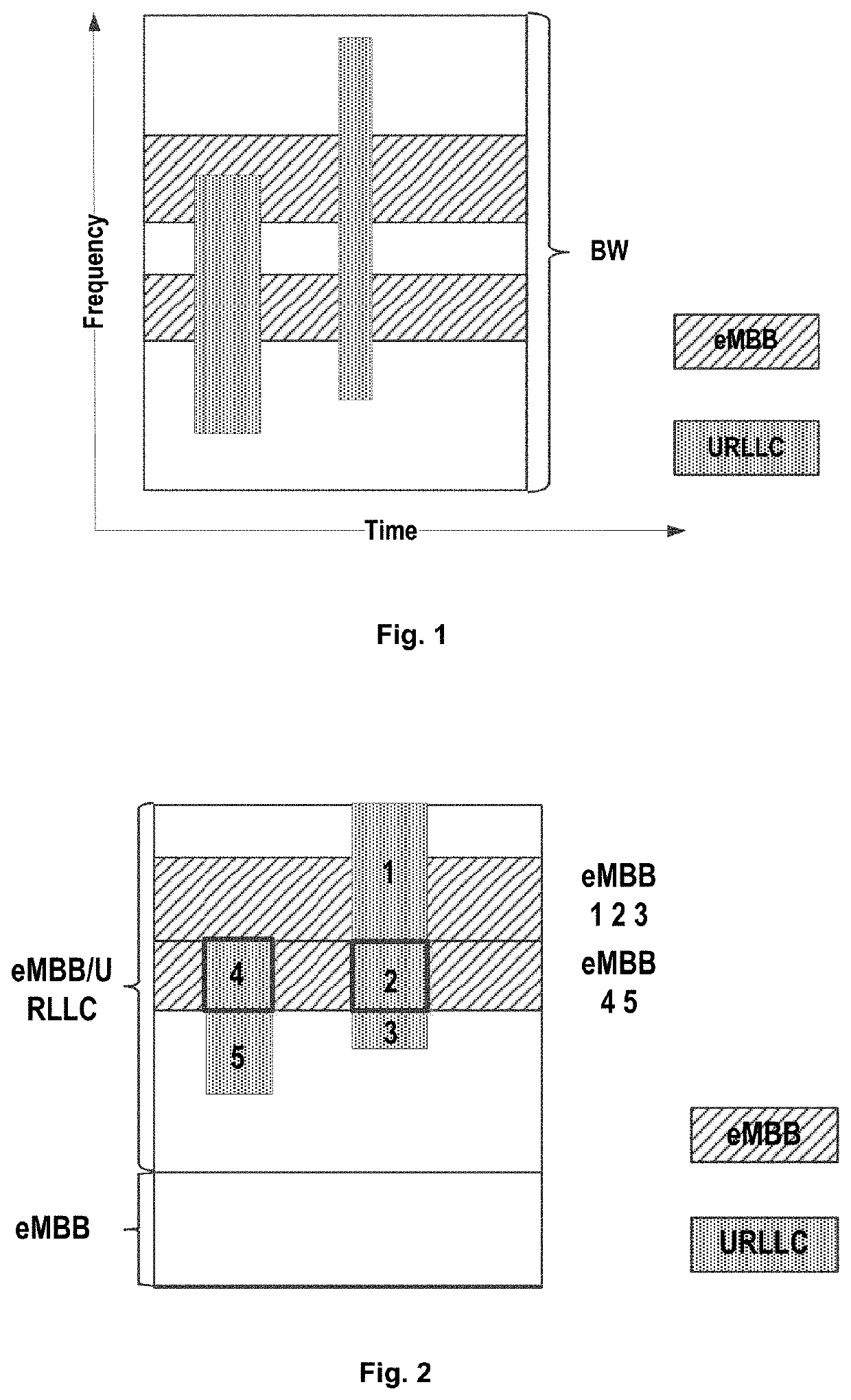
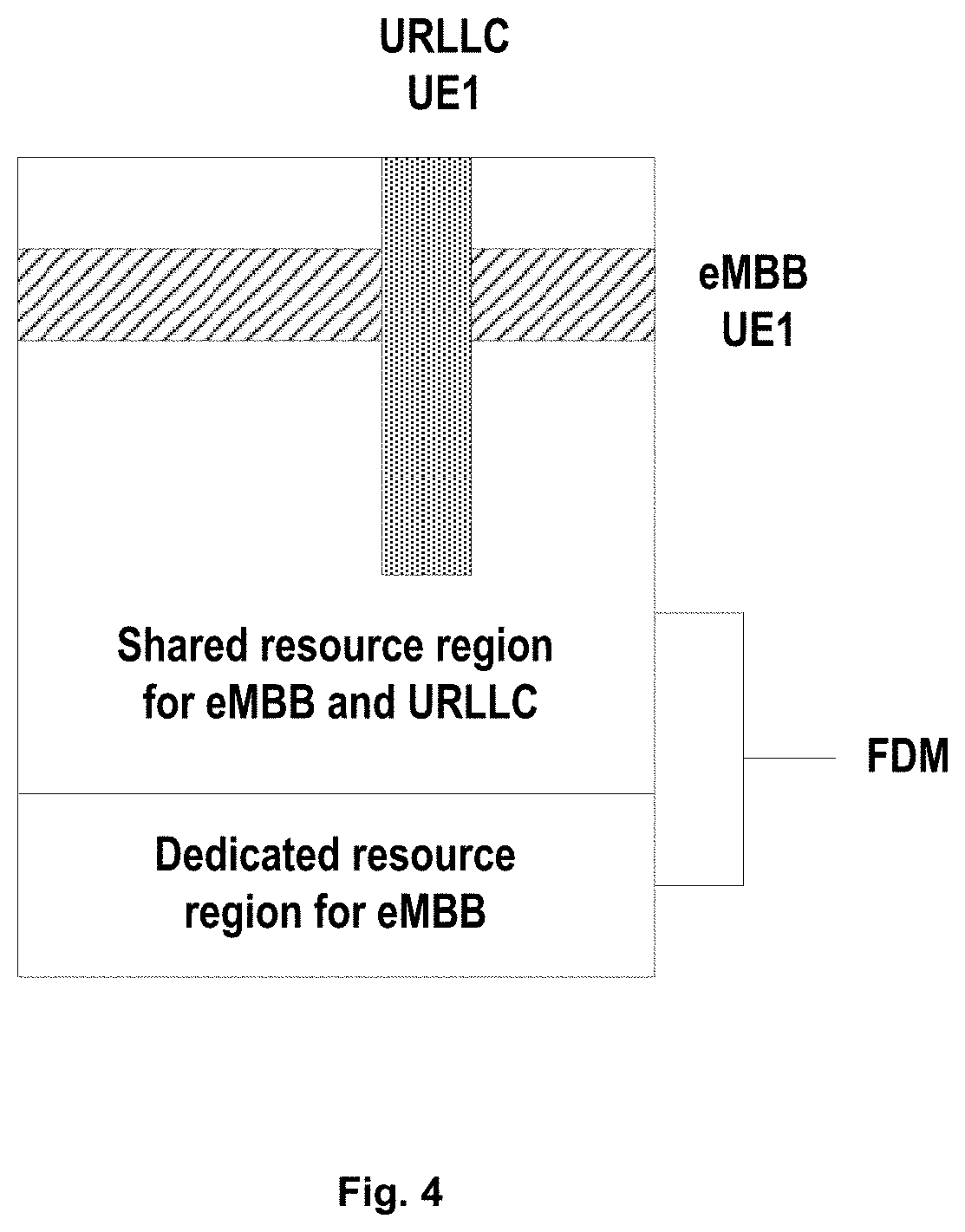
CROSS REFERENCE TO RELATED APPLICATIONS[0001]This application is a National Stage of International Application No. PCT / CN2017 / 099510 filed Aug. 29, 2017.FIELD OF THE INVENTION[0002]The non-limiting and exemplary embodiments of the present disclosure generally relate to the field of wireless communication techniques, and more particularly relate to a method, network device, and apparatus for transmitting a preemption indication and a method, terminal device, and apparatus for receiving a preemption indication.BACKGROUND OF THE INVENTION[0003]New radio access system, which is also called as NR system or NR network, is the next generation communication system. In Radio Access Network (RAN) #71 meeting for the third generation Partnership Project (3GPP) working group, study of the NR system was approved. The NR system will consider frequency ranging up to 100 Ghz with an object of a single technical framework addressing all usage scenarios, requirements and deployment scenarios defined ...

Claims


Application Information

Patent Timeline
Patent Type & Authority Patents(United States)
IPC IPC(8): H04W72/04H04W76/27
CPCH04W72/0493H04W72/042H04W72/0453H04W76/27H04W72/569H04W72/23H04W72/53
Inventor MIAO, ZHAOBANGGAO, YUKAIWANG, GANG
Owner NEC CORP
Learn More