Method for diagnosing a vacuum actuator

a vacuum actuator and diagnostic method technology, applied in the direction of machines/engines, electric control, combustion air/fuel air treatment, etc., can solve the problems of inability to accurately diagnose the degradation of the vacuum actuator, increase maintenance costs, and unnecessary testing and expenses, so as to reduce the needless and costly diagnostics, accurate determination, and the effect of reducing the number of diagnostic routines

Active Publication Date: 2017-10-24
FORD GLOBAL TECH LLC
View PDF15 Cites 0 Cited by
  • Summary
  • Abstract
  • Description
  • Claims
  • Application Information

AI Technical Summary

Benefits of technology

[0006]In this way, degradation of a vacuum actuator may be more accurately determined based on estimating a total amount of vacuum fill in a vacuum reservoir coupled to the vacuum actuator. By determining that an available quantity of vacuum in the vacuum reservoir is lower than a desired quantity, non-responsiveness of the vacuum actuator may be attributed to a lack of vacuum in the vacuum reservoir. Accordingly, indications of vacuum actuator degradation during diagnostic routines may be diminished, particularly when vacuum fill in the vacuum reservoir is lower than desired. As such, diagnostic routines may be completed without a malfunction indicator light being actuated. This in turn may reduce needless and costly diagnostics, and unnecessary maintenance from being carried out.

Problems solved by technology

However, diagnostic tests may incorrectly diagnose the vacuum actuator as degraded when adequate vacuum is not available to actuate the vacuum actuator.
As such, incorrect diagnoses may result in false diagnostic codes being set which can lead to unnecessary testing and expenses.
Overall, maintenance costs may increase leading to customer dissatisfaction.
If the amount of vacuum fill in the vacuum reservoir is estimated to be lower than a threshold level, adequate vacuum may not be available to actuate the CMCV(s).

Method used


Image

  • Method for diagnosing a vacuum actuator
  • Method for diagnosing a vacuum actuator
  • Method for diagnosing a vacuum actuator

Examples


Embodiment Construction

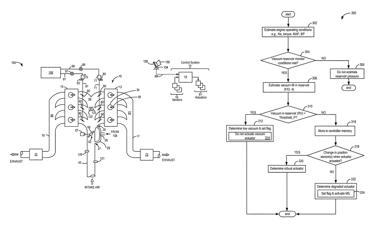
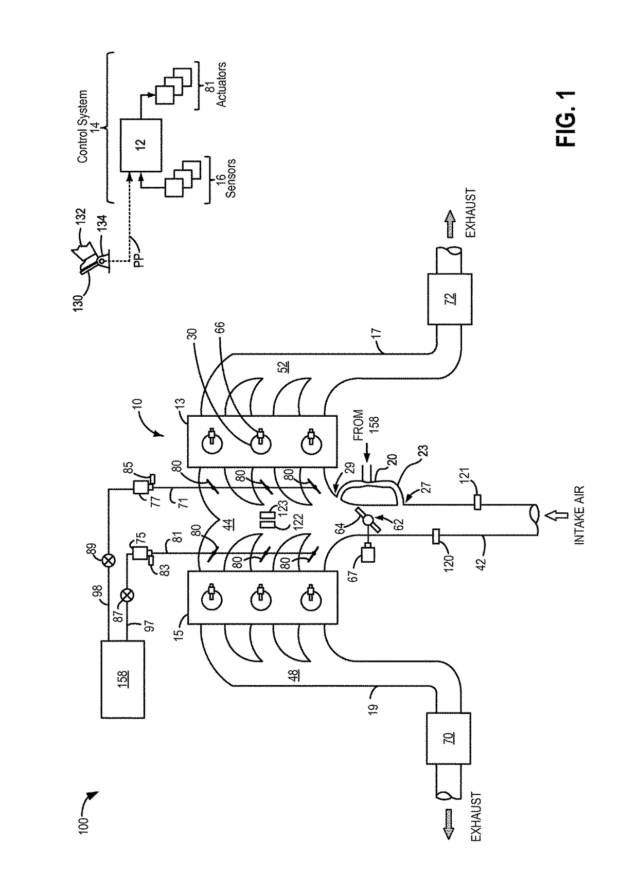
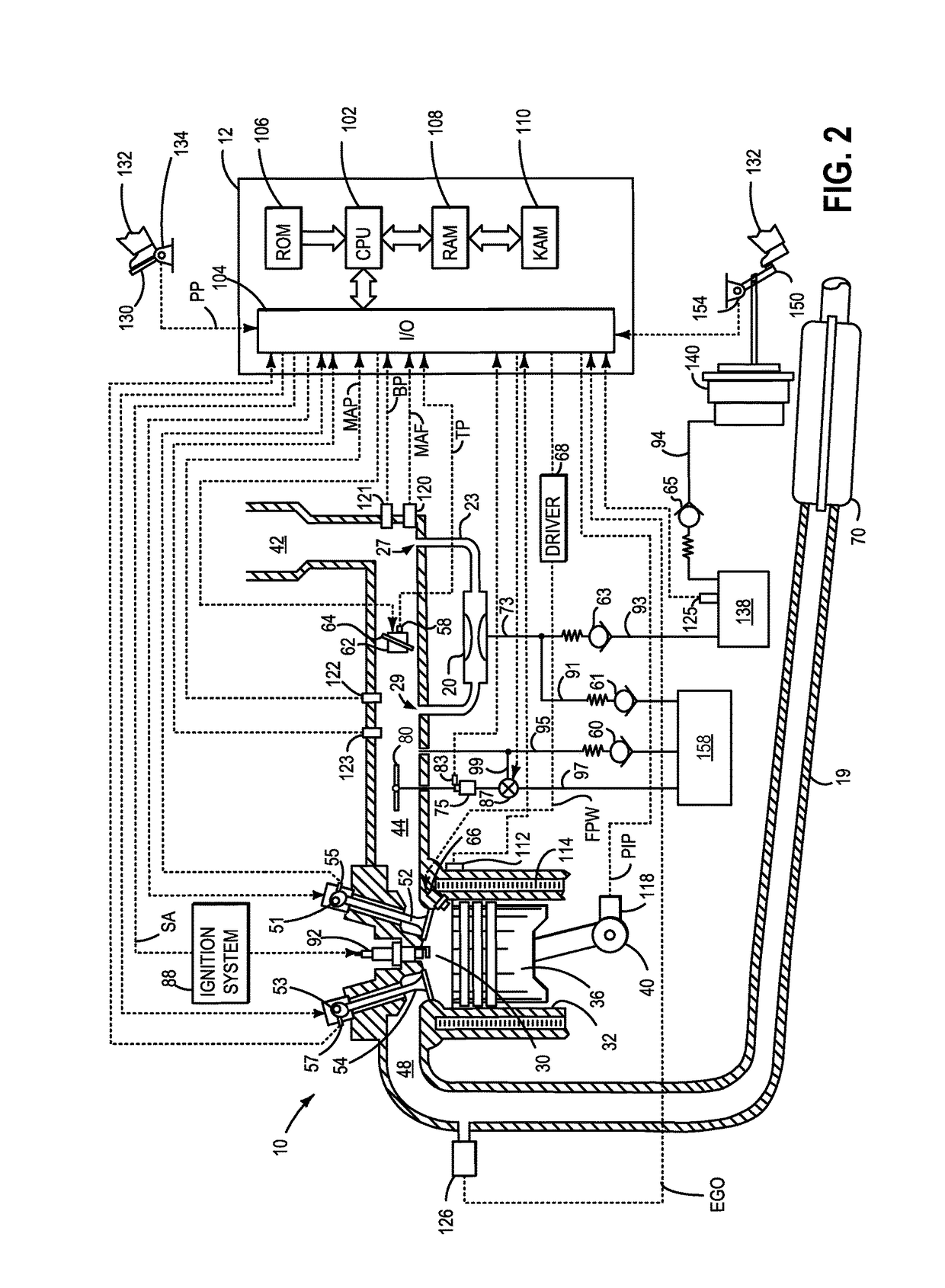
[0014]The following description relates to systems and methods for determining degradation in a vacuum actuated valve, such as a charge motion control valve (CMCV), positioned in an intake of an engine system, such as the engine depicted in FIGS. 1 and 2. An actuator of the vacuum actuated valve may receive vacuum from either an engine intake manifold or a vacuum reservoir. Degradation of the actuator and / or vacuum actuated valve may be indicated when the vacuum actuated valve does not change position upon actuation. However, an actuation command may not result in a corresponding change in valve position if sufficient vacuum is not available in the vacuum reservoir to actuate the valve. An amount of vacuum fill in the vacuum reservoir may be modeled by estimating air flow into and out of the vacuum reservoir (FIGS. 4a, 4b, and 5). A diagnosis of the vacuum actuated valve may be based upon the estimated amount of vacuum fill in the vacuum reservoir (FIG. 3) such that the vacuum actua...


PUM


Abstract

Methods and systems are described for diagnosing degradation of a vacuum actuator in an engine system. An example method comprises indicating degradation of the vacuum actuator based on an estimate of flow of air into and out of a vacuum reservoir. The estimate is further based on flow of air generated via each of an aspirator in the intake system, an actuation of the vacuum actuator, and leakage during the actuation of the vacuum actuator.

Description

TECHNICAL FIELD[0001]The present application relates to evaluating a vacuum actuator based on available vacuum fill in a vacuum reservoir.BACKGROUND AND SUMMARY[0002]Vacuum may be used to operate or to assist in the operation of various devices of a vehicle. For example, vacuum may be used to assist a driver applying vehicle brakes, fuel vapor purging, heating and ventilation system actuation, and actuation of various valves such as a wastegate, a charge motion control valve (CMCV), etc. CMCVs may be coupled upstream of intake valves of engine cylinders in order to increase or decrease the charge motion of a corresponding cylinder, thereby increasing or decreasing the cylinder burn rate, respectively. Vacuum to actuate these valves may be obtained from an engine intake manifold in normally aspirated engines because the intake manifold pressure is often at a pressure lower than atmospheric pressure. When vacuum in the engine intake manifold is not sufficient, vacuum to actuate these ...

Claims


Application Information

Patent Timeline
Patent Type & Authority Patents(United States)
IPC IPC(8): F02D41/22F02D41/18F02D41/00F02M35/10F02M35/104
CPCF02D41/221F02D41/18F02D41/0002Y02T10/40F02D2200/0414F02M35/104F02M35/10229F02D2200/0406F02D2250/41F02D41/22F02M35/10
Inventor MARTIN, DOUGLAS RAYMONDFOURNELLE, GILBERT
Owner FORD GLOBAL TECH LLC
Why Eureka
Try Eureka