System and method for health monitoring of electrical systems

a technology for electrical systems and health monitoring, applied in the field of system and method for health monitoring of electrical systems, can solve the problems of large and complex modern aircraft electrical wiring systems, high maintenance costs, waste of time, etc., and achieve the effect of reducing false positive fault indications

Inactive Publication Date: 2019-07-09
SIKORSKY AIRCRAFT CORP
View PDF12 Cites 0 Cited by
  • Summary
  • Abstract
  • Description
  • Claims
  • Application Information

AI Technical Summary

Benefits of technology

[0006]Additionally or alternatively, in this or other embodiments the difference TDR waveform is normalized and an exponential moving average TDR waveform is calculated from the normalized difference TDR waveform. The difference energy is calculated utilizing the exponential moving average TDR waveform to reduce false positive fault indications.
[0016]Additionally or alternatively, in this or other embodiments the TDR signal processor is configured to normalize the difference TDR waveform, calculate an exponential moving average TDR waveform from the normalized difference TDR waveform and calculate the difference energy utilizing the exponential moving average TDR waveform to reduce false positive fault indications.

Problems solved by technology

Modern aircraft have large and complex electrical wiring systems, which contain miles of wire and thousands of interconnects.
These systems are expensive and time consuming to maintain.
Typically, a wire fault affects other systems on the aircraft, which draws the attention of maintainers.
They focus on the equipment, which can result in wasted time and the false removal of expensive systems, before they focus on the wiring.
Wires are often routed in hard to reach areas of the aircraft, reducing the ability to conduct a visual inspection for faults or wire condition.
The current fleet of deployed aircraft has very little technology to detect and isolate wire faults.
Previous technology includes sensors to detect wiring faults, but few have been fully integrated into the aircraft.

Method used


Image

  • System and method for health monitoring of electrical systems
  • System and method for health monitoring of electrical systems
  • System and method for health monitoring of electrical systems

Examples


Embodiment Construction

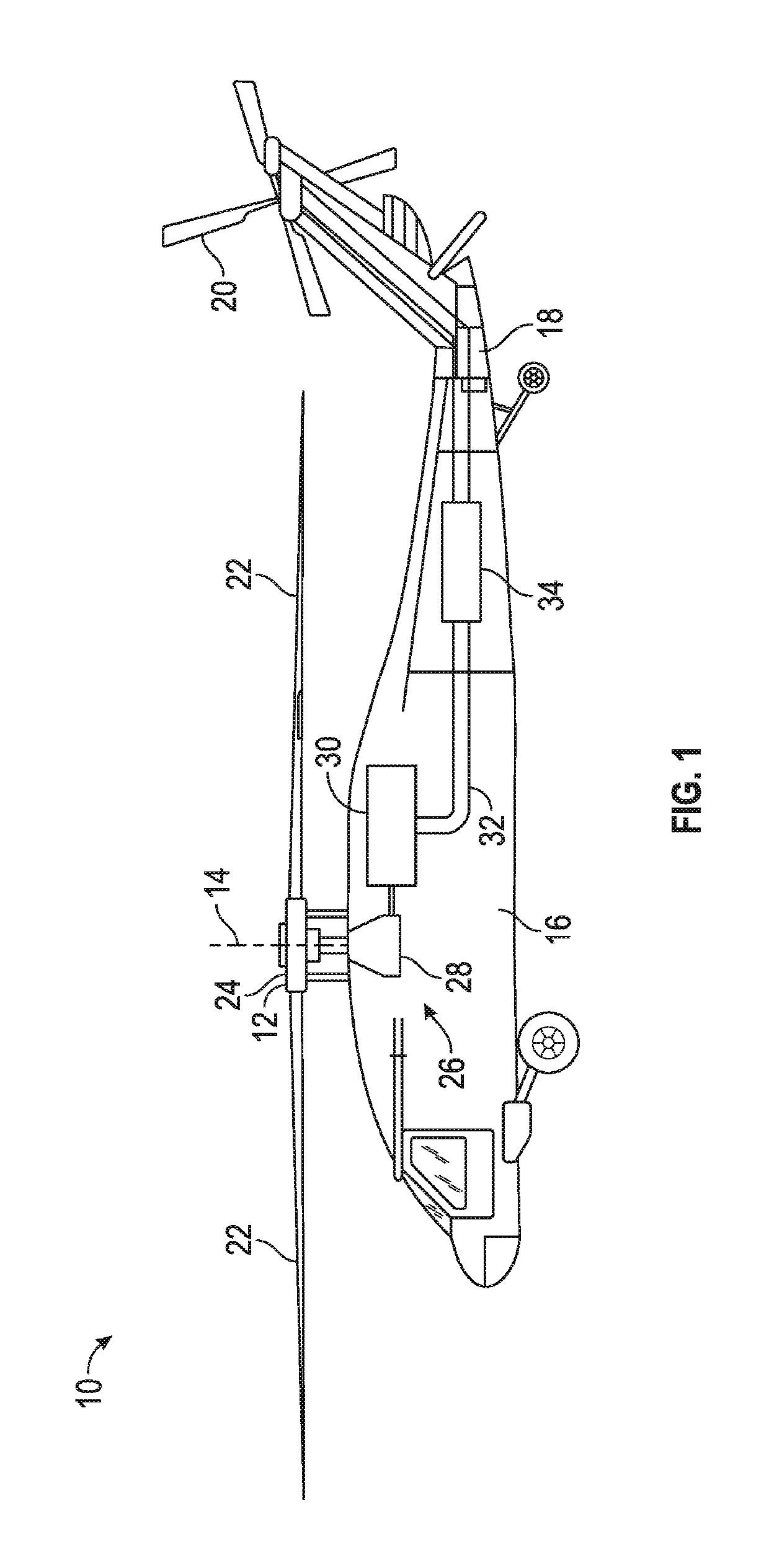
[0032]FIG. 1 illustrates an exemplary rotary-winged aircraft 10 having a main rotor system 12, which rotates about a rotor axis 14. The aircraft 10 includes an airframe 16 which supports the main rotor system 12 as well as an extending tail 18 including a tail rotor 20. The main rotor system 12 includes a plurality of rotor blade assemblies 22 mounted to a rotor hub assembly 24. The main rotor system 12 is driven by a transmission 26. The transmission 26 includes a main gearbox 28 driven by one or more engines, illustrated schematically at 30. The main gearbox 28 and engines 30 are considered as part of the non-rotating frame of the aircraft 10. In the case of a rotary wing aircraft, the main gearbox 28 may be interposed between one or more gas turbine engines 30 and the main rotor system 12. The aircraft further includes a tail rotor shaft 32 and tail rotor gearbox 34 connected to the transmission 26 to drive rotation of the tail rotor 20. The aircraft 10 further includes an electr...


PUM


Abstract

A method of electrical system fault detection and location determination includes measuring a baseline time domain reflectometry (TDR) waveform along a wire path of the electrical system and obtaining an operating TDR waveform along the wire path. The operating TDR waveform is compared to the baseline TDR waveform to derive a difference TDR waveform, and a difference energy is calculated utilizing the difference TDR waveform. The difference energy is monitored over time for peaks in the difference energy and potential electrical system faults are identified via the peaks in the difference energy.

Description

CROSS-REFERENCE TO RELATED APPLICATIONS[0001]The present application claims priority to U.S. Provisional Application No. 61 / 974,066 filed on Apr. 2, 2014, and PCT Application No. US2015 / 022730, filed on Mar. 26, 2015, the contents of which are incorporated by reference herein in their entirety.FEDERAL RESEARCH STATEMENT[0002]This invention was made with government support with the United States Army under Contract No. W911 W6-10-2-0006. The government therefore has certain rights in this invention.BACKGROUND[0003]Modern aircraft have large and complex electrical wiring systems, which contain miles of wire and thousands of interconnects. These systems are expensive and time consuming to maintain. Typically, a wire fault affects other systems on the aircraft, which draws the attention of maintainers. They focus on the equipment, which can result in wasted time and the false removal of expensive systems, before they focus on the wiring. With the number of electrical and avionics system...

Claims


Application Information

Patent Timeline
Patent Type & Authority Patents(United States)
IPC IPC(8): G01R31/00G01R31/11
CPCG01R31/11G01R31/008
Inventor DROST, BRIANWINSTON, HOWARD A.MASTRIANNI, MICHAEL G.MANIACI, ANTHONY SANTOPALLADINO, ANDREW
Owner SIKORSKY AIRCRAFT CORP
Why Eureka
Try Eureka