Enhanced carrier aggregation scheduling method and device in user equipment and base station

a carrier aggregation and user equipment technology, applied in the direction of electrical equipment, wireless communication, etc., can solve the problems of reducing increasing the total number of bits, and occupying more air interface resources by the dci, so as to achieve optimally maintaining compatibility with the existing system, improving the receiving performance of the dci, and conserving an air interface resource

Active Publication Date: 2019-09-10
SISVEL INT
View PDF4 Cites 0 Cited by
  • Summary
  • Abstract
  • Description
  • Claims
  • Application Information

AI Technical Summary

Benefits of technology

[0018]The character of the above method is that: a value of the fourth index in a given DCI of the serving cell scheduled by the given DCI is related to a transmitting serving cell of the given DCI. The fourth index of the given DCI only indicates the serving cell scheduled by the transmitting serving cell and does not need to indicate all serving cells configured for the UE, thereby reducing an indication of a number of bits needed for the fourth index.
[0056]Compared to the existing technique, the present disclosure reduces a number of bits of downlink control information (DCI), thus conserving an air interface resource, or improving the receiving performance of the DCI. Furthermore, the present disclosure instructs the third index not to modify the number of bits of the DCI by utilizing an existing carrier indicator field (CIF), thus maximally maintaining compatibility with an existing system.

Problems solved by technology

However, the above intuitive method causes an increase of total number of bits of DCI, thereby occupying more air interface resources by the DCI or reducing the receiving performance of the DCI.
The inventor researches and discovers that in enhanced CA scenario, it is limited by a limitation of a PUCCH (physical downlink control channel) capacity, too many carriers may hardly be scheduled on one carrier.

Method used


Image

  • Enhanced carrier aggregation scheduling method and device in user equipment and base station
  • Enhanced carrier aggregation scheduling method and device in user equipment and base station
  • Enhanced carrier aggregation scheduling method and device in user equipment and base station

Examples


embodiment i

[0063

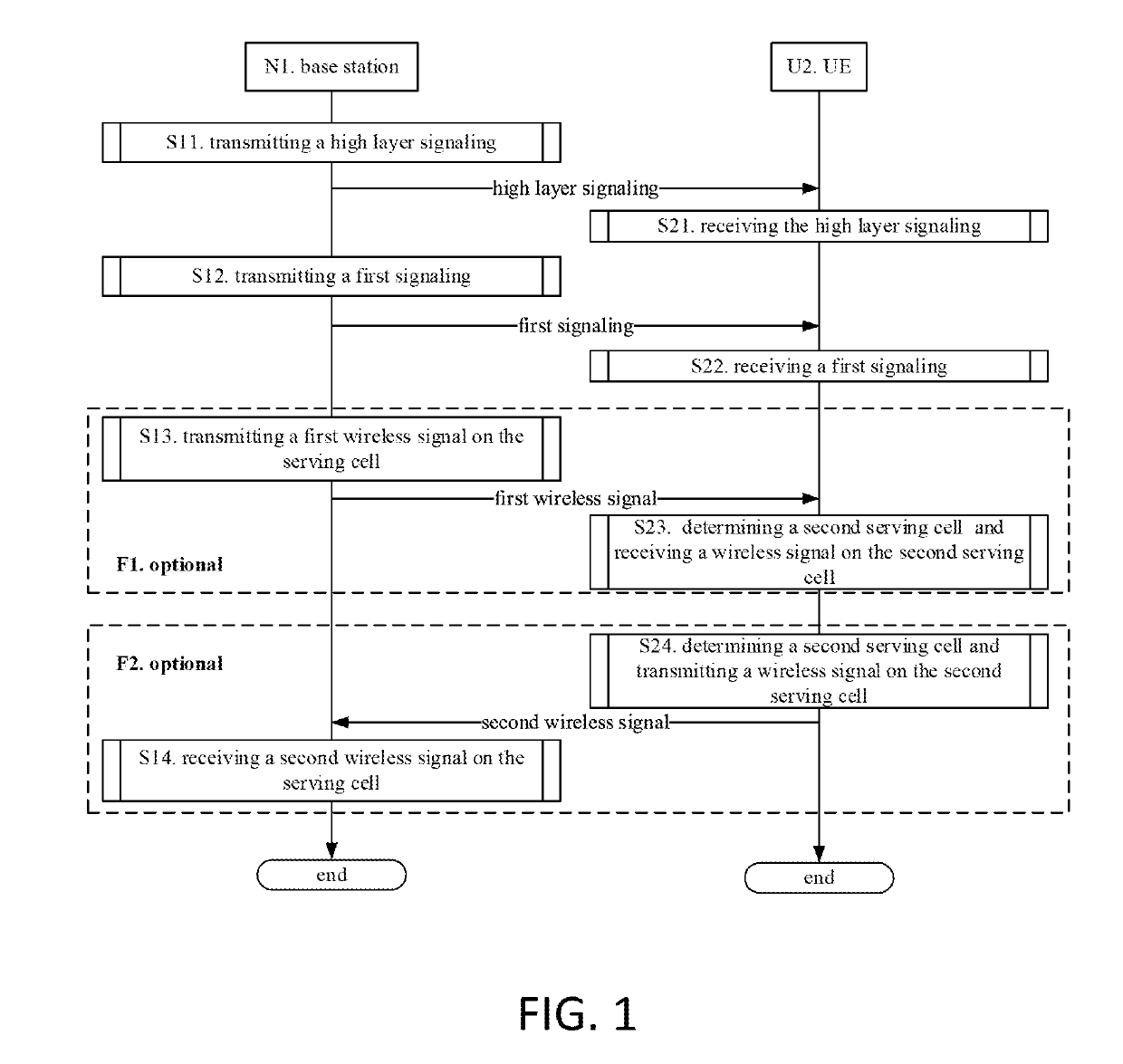
[0064]Embodiment I illustrates a flowchart of transmitting a wireless signal, as shown in FIG. 1. In FIG. 1, a base station N1 maintains a serving base station of a UE U2, the steps identified by a square frame F1 and a square frame F2 are mutually exclusive, i.e. (the step in) the square frame F1 and (the step in) the square frame F2 do not appear at the same time.

[0065]For the base station N1, in step S11, the method involves transmitting a high layer signaling to indicate K sets of configuration information, the K sets of configuration information correspond to K serving cells respectively, and the configuration information including a first index, a second index, a third index and the working frequency band information. In step S12, the method involves transmitting a first signaling on a first serving cell, the first signaling including a fourth index and the scheduling information. In step S13, the method involves transmitting the first wireless signal on the serving cell ...

embodiment ii

[0074

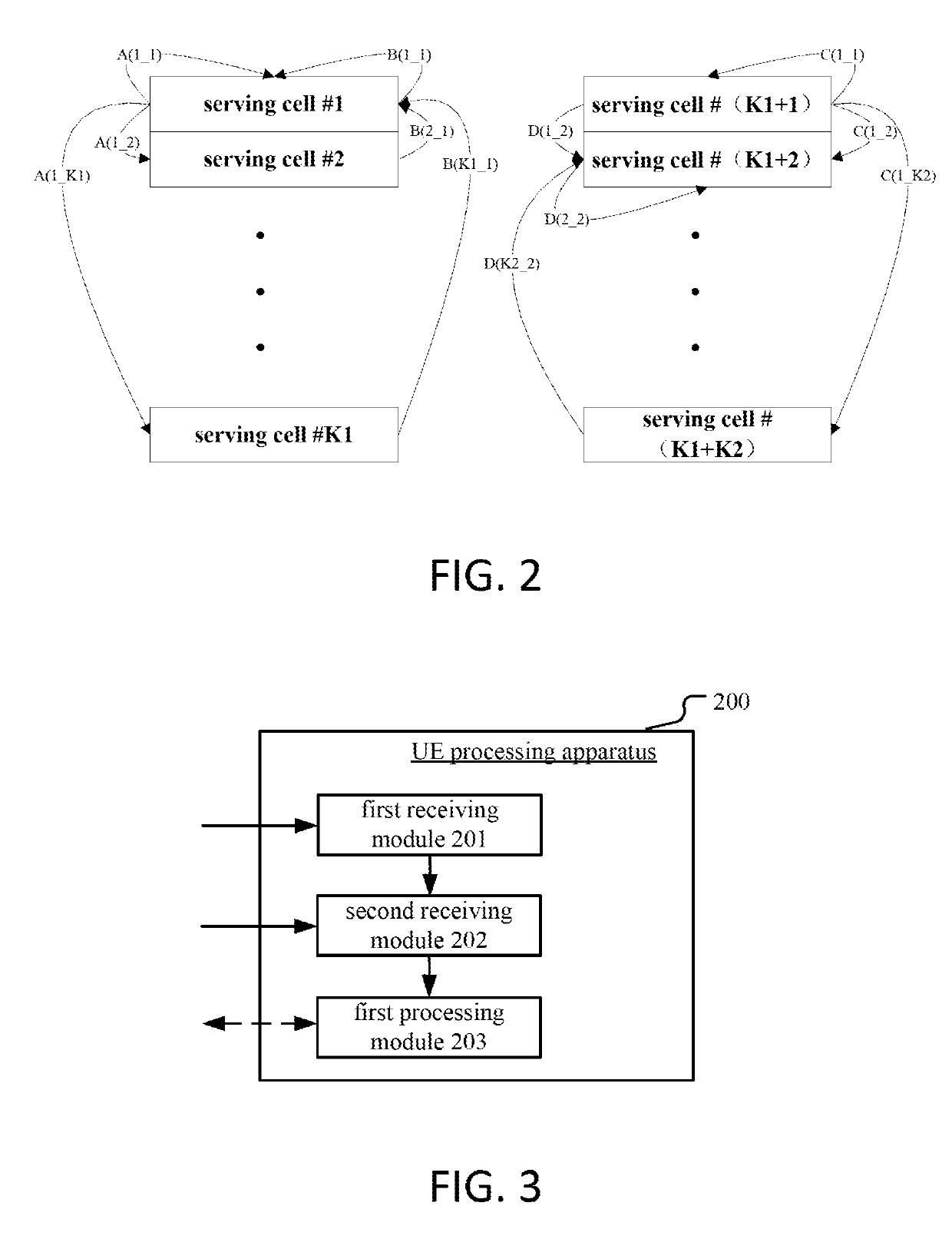
[0075]Embodiment II is a diagram illustrating a distribution of the scheduling signaling and PUCCH, as shown in FIG. 2. In FIG. 2, the arrows identified by A and C indicates a downlink scheduling signaling, and the arrows identified by B and D indicated a PUCCH transmission.

[0076]The base station transmits a high layer signaling to a target UE, the high layer signaling indicates (K1+K2) sets of the configuration information, the (K1+K2) sets of the configuration information correspond to (K1+K2) serving cells respectively, the configuration includes a first index, a second index, a third index and the working frequency band information. The (K1+K2) serving cells correspond to serving cells #1-#(K1+K2) in FIG. 2. For the serving cells #1-#(K1+K2), the first indexes of the corresponding configuration information are 0, 1, . . . , K1+K2−1 respectively.

[0077]For the target UE, the second indexes of the configuration information corresponding to the serving cells #1−#K1 are 0 (equal...

embodiment iii

[0085

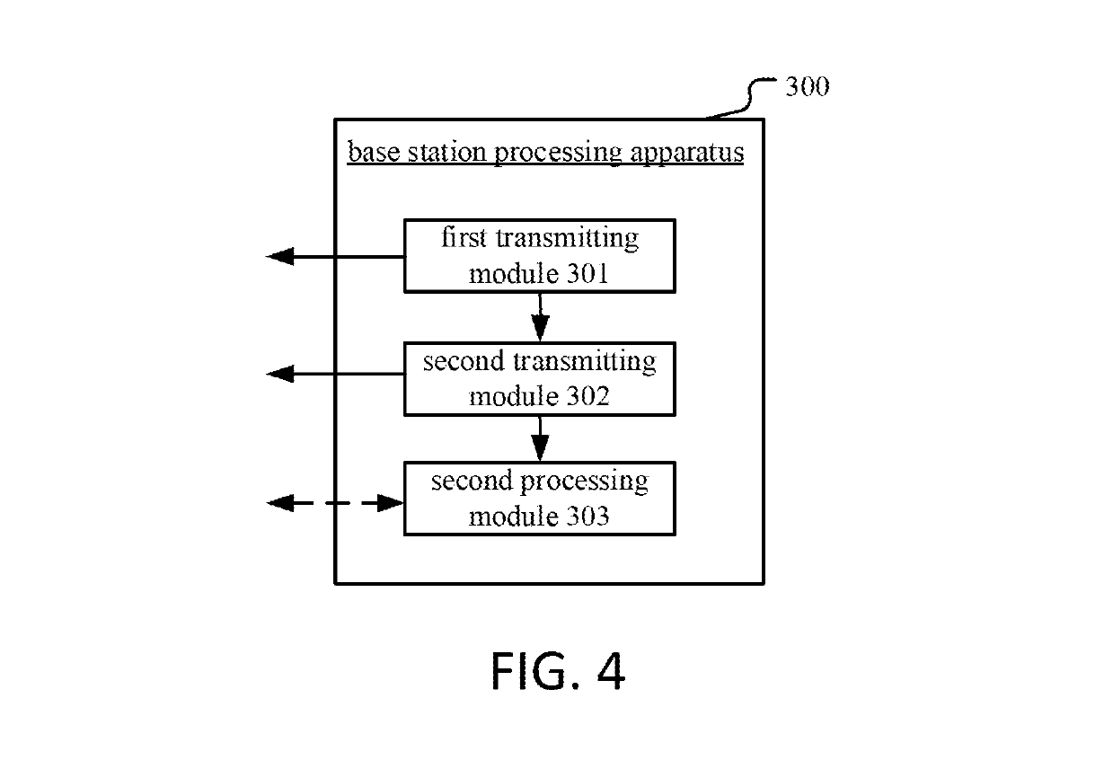
[0086]Embodiment III is a structure diagram illustrating a processing apparatus used in a UE, as shown in FIG. 3. In FIG. 3, the UE processing apparatus 200 in the UE includes a first receiving module 201, a second receiving module 202, and a first processing module 203.

[0087]The first receiving module 201 is used for receiving a high layer signaling to determine K sets of configuration information, the K sets of configuration information correspond to K serving cells respectively, and the configuration information comprising a first index, a second index, a third index and the working frequency band information. The second receiving module 202 is used for receiving a first signaling on a first serving cell, the first signaling comprising a fourth index and the scheduling information. The first processing module 203 is used for determining a second serving cell according to a first set of the configuration information and the fourth index of the first signaling, and transportin...


PUM


Abstract

Disclosed are an enhanced carrier aggregation (CA) scheduling method and device in a user equipment (UE) and a base station, the method comprising: in a first step, a UE receives a high-level signaling determining K sets of configuration information, the configuration information comprising {a first index, a second index, a third index, and working frequency band information}; in a second step, the UE receives, at a first service cell, a first signaling, the first signaling comprising a fourth index and scheduling information; and in a third step, the UE determines a second service cell according to first configuration information and the fourth index in the first signaling. The present disclosure reduces the number of bits in downlink control information (DCI), thus conserving an air interface resource, or improving the receiving performance of the DCI. Furthermore, the present disclosure instructs the third index not to modify the number of bits of the DCI by utilizing an existing carrier indicator field (CIF), thus maximally maintaining compatibility with an existing system.

Description

CROSS REFERENCE TO RELATED APPLICATIONS[0001]This application is a U.S. National Phase application under 35 U.S.C. § 371 of International Application No. PCT / CN2015 / 099255, filed on Dec. 28, 2015, and claims benefit to Chinese Patent Application No. CN201410852934.8, filed on Dec. 26, 2014, all of which is hereby incorporated by reference for all purposes. The International Application was published on Jun. 30, 2016 as WO2016101928A1 under PCT Article 21 (2).BACKGROUND[0002]Technical Field[0003]The present disclosure is related to a scheme for scheduling a carrier aggregation (CA), and more particular to a scheme for scheduling the CA based on Long Term Evolution (LTE) system.[0004]Related Art[0005]In the traditional LTE system R (release) 10 developed by 3GPP (3rd Generation Partner Project), the CA is introduced as one of the key techniques, a main idea is that user equipment (UE) may work on a plurality of carriers at the same time, and the CA may improve peak value rate of a sin...

Claims


Application Information

Patent Timeline
Patent Type & Authority Patents(United States)
IPC IPC(8): H04W72/12H04W72/04
CPCH04W72/12H04W72/04H04W72/0413H04W72/042H04W72/1289H04W72/0453H04W72/23H04W72/21
Inventor ZHANG, XIAOBO
Owner SISVEL INT
Why Eureka
Try Eureka