Stirring rod of hot and cold foods supplying machine and assembled stirring unit thereof

a technology of hot and cold foods and stirring rods, which is applied in the direction of manufacturing tools, mould handling/dressing devices,foundry moulding apparatuses, etc., can solve the problems of deformation and crushing of stirring blades, and achieve the effect of rotating and stirring more stably

Active Publication Date: 2022-04-19
MAING CHAU ENTERPRISE CO LTD
View PDF14 Cites 0 Cited by
  • Summary
  • Abstract
  • Description
  • Claims
  • Application Information

AI Technical Summary

Benefits of technology

[0016]The following effects are preferably achieved according to the above-mentioned technical features:
[0018]2. The stirring blades collectively form a non-sealed spiral blade with notch(es) disposed about the axial direction, so that food materials are subjected to less pressure even when they are at a front end of a discharge cylinder; therefore, the stirring rod of the present invention is capable of generating the effect of spiral stirring, while at the same time the food materials at the front end of the discharge cylinder are not squashed due to excessive pressure, and the stirring blade is not deformed and damaged due to an excessive squeezing force.

Problems solved by technology

Further, food materials close to the discharge end are squashed due to a great pressure or a pushing force by the conventional stirring blades in sealed spiral contours when the food materials are pushed from a feeding end to a discharge end; and so the stirring blades are inadequate to be used on food materials which require a sense of granules, whereby the great pressure sometimes even causes the stirring blades to be crushed and deformed.

Method used


Image

  • Stirring rod of hot and cold foods supplying machine and assembled stirring unit thereof
  • Stirring rod of hot and cold foods supplying machine and assembled stirring unit thereof
  • Stirring rod of hot and cold foods supplying machine and assembled stirring unit thereof

Examples


Embodiment Construction

[0034]In summary of the above-mentioned technical features, the main effects of a stirring rod of hot and cold foods supplying machine and an assembled stirring unit thereof can be clearly presented by the following embodiments.

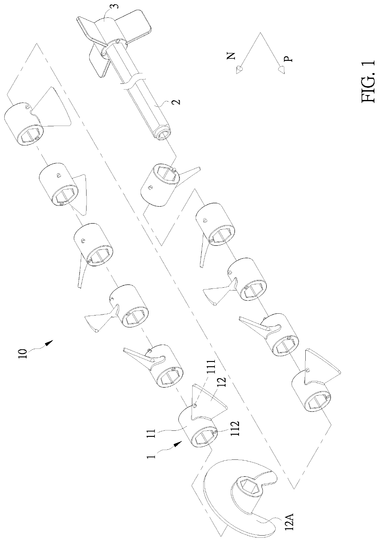
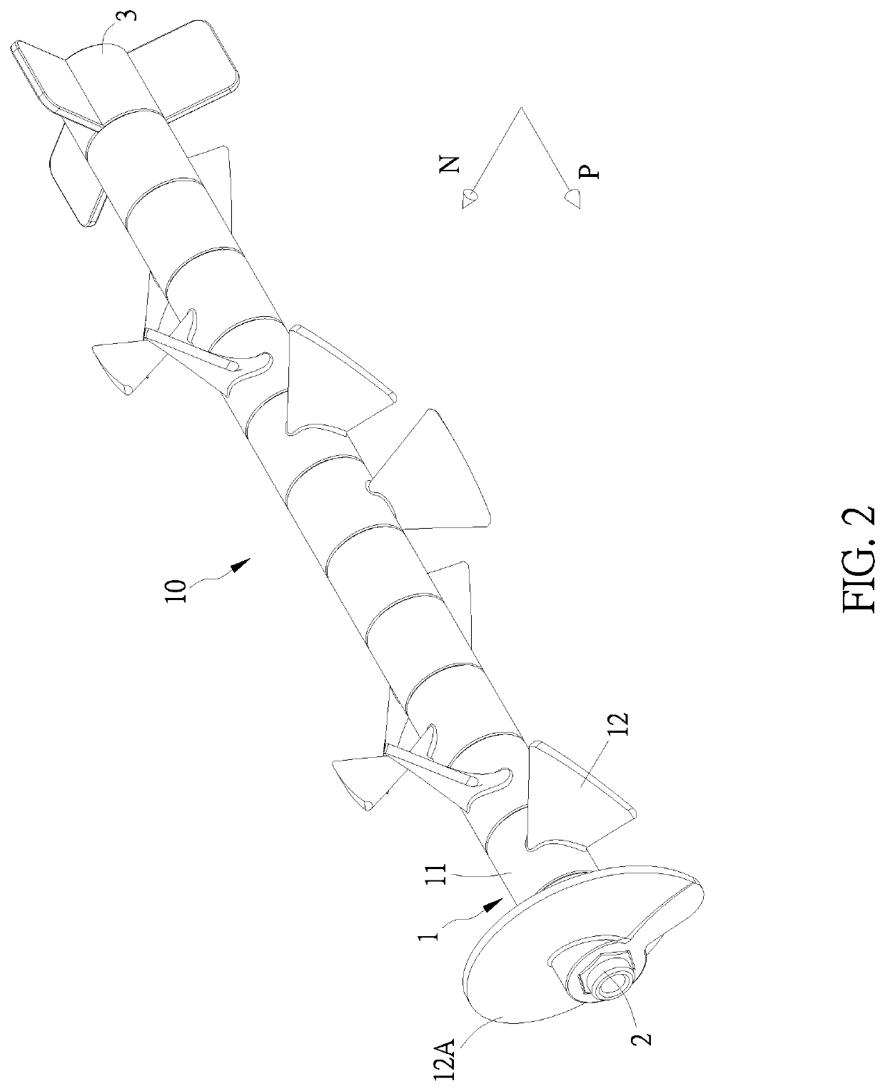
[0035]Referring to FIGS. 1 and 2, a stirring rod (10) of the embodiment includes multiple assembled stirring units (1), an assembly rod (2), and a base (3) serially connected along an axial direction (P), in which each assembled stirring unit (1) includes an assembled piece (11) and a stirring blade (12), wherein:

[0036]a direction along the length of the assembled piece (11) is the axial direction (P), a direction perpendicular to the axial direction (P) is a radial direction (N), and the assembled piece (11) has a first joining piece (111) and a second joining piece (112) respectively at two ends thereof in the axial direction (P). The stirring blade (12) is disposed on the assembled piece (11) and extends towards the radial direction (N); the stirring blade...


PUM


Abstract

The present invention relates to a stirring rod of hot and cold foods supplying machine and an assembled stirring unit thereof. The assembled stirring unit includes an assembled piece and a stirring blade, wherein a length direction of the assembled piece is an axial direction, a direction perpendicular to the axial direction is a radial direction, and the assembled piece has a first joining piece and a second joining piece respectively at two ends thereof in the axial direction. The stirring blade is provided on the assembled piece and extends towards the radial direction, and the stirring blade is twisted at an angle by having the radial direction as an axis. The stirring rod is formed by serially connecting multiple assembled stirring units along the axial direction.

Description

CROSS REFERENCES TO RELATED APPLICATIONS[0001]The present application claims priority from Taiwanese Patent Application Serial Number 108203311, filed Mar. 19, 2019 the disclosure of which is hereby incorporated by reference herein in its entirety.BACKGROUND OF THE INVENTION(a) Field of the Invention[0002]The present invention is related to a stirring rod of hot and cold foods supplying machine and an assembled stirring unit thereof and, more particularly, to an invention in which the stirring rod is formed by assembling multiple assembled stirring units and stirring blades of each assembled stirring unit are presented in specific twisting contour.(b) Description of the Prior Art[0003]In order to conveniently and quickly manufacture processed food materials, various food processors are available commercially, and one of the important core components in the food processors is the stirring rod; the stirring rod is capable of uniformly mixing different food materials, as well as ensuri...

Claims


Application Information

Patent Timeline
Patent Type & Authority Patents(United States)
IPC IPC(8): B22C5/00B01F27/191B01F27/1125B01F27/114B01F27/1144B01F101/06
CPCB01F27/191B01F27/1125B01F27/1141B01F27/1144B01F2101/06B01F2215/0422B01F27/0723B01F27/071B01F27/0724B01F27/1921B01F27/72B01F27/70B01F35/561B01F35/75455B01F35/92
Inventor KO, YONG-TENG
Owner MAING CHAU ENTERPRISE CO LTD
Why Eureka
Try Eureka