Compact low flow rate fluidic nozzle for spraying and cleaning applications having a reverse mushroom insert geometry

a low flow rate, fluidic nozzle technology, applied in vehicle cleaning, vehicle components, optical viewing, etc., can solve the problems of reducing the high viscosity yaw, roll, and limited performance of the fluidic nozzle insert, and achieve the desired level of performance

Active Publication Date: 2022-04-19
DLHBOWLES INC
View PDF76 Cites 0 Cited by
  • Summary
  • Abstract
  • Description
  • Claims
  • Application Information

AI Technical Summary

Benefits of technology

[0016]The invention relates to various low flow rate fluidic nozzle inserts having a reverse mushroom-shaped mushroom insert geometry that are useful for a wide range of spraying and cleaning applications. In one embodiment, the present invention relates to fluidic nozzle inserts that are able to perform at low flow rates with geometrical and dimensional limitations. In still another embodiment, the present invention relates to compact fluidic nozzle inserts that provide a manner by which to attain a desired level of performance in a fluidic nozzle assembly for small scale applications at low flow rates.
[0017]In one embodiment, the present invention relates to a fluidic nozzle assembly having therein at least one compact fluidic nozzle insert (e.g., one having a width of about 5.5 mm or less, and a length of 5 mm or less). Nozzle assemblies that contain one or more compact fluidic nozzle inserts are found to be uniquely effective for applications with very limited space due to visibility / aesthetic reasons. Usually a fluidic nozzle insert is limited by a minimum size requirement to successfully generate fluidic oscillations, which in turn produces a spray. The compact fluidic nozzle insert of the present invention has new features that enable fluidic operation in a smaller size (than previously known or available) to produce a spray fan at low flow rates. Typical flow rates are less than 300 mL / min at 25 psi. It is also characterized by high velocity, large drops, uniform distribution and improved high viscosity operation.
[0018]In one particular instance, the compact fluidic nozzle assembly of the present invention includes a compact housing configured to receive, aim and provide fluid communication to a fluid source and a fluidic nozzle insert or chip which, when assembled, incorporates features that alleviates the performance issues that occur in smaller scale fluidic nozzles. These characteristics include reduction in spray instability and improvement in high viscosity performance.
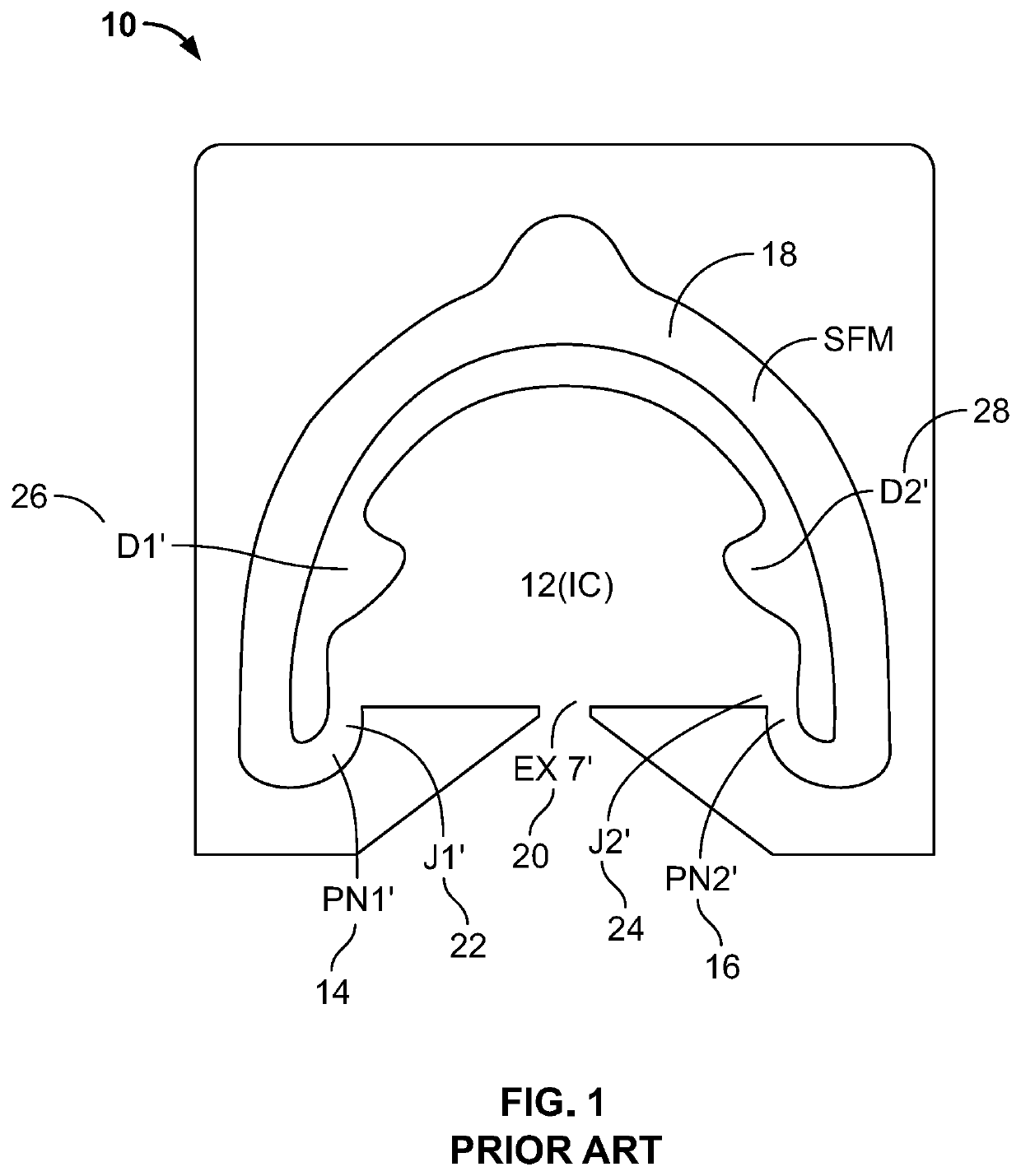
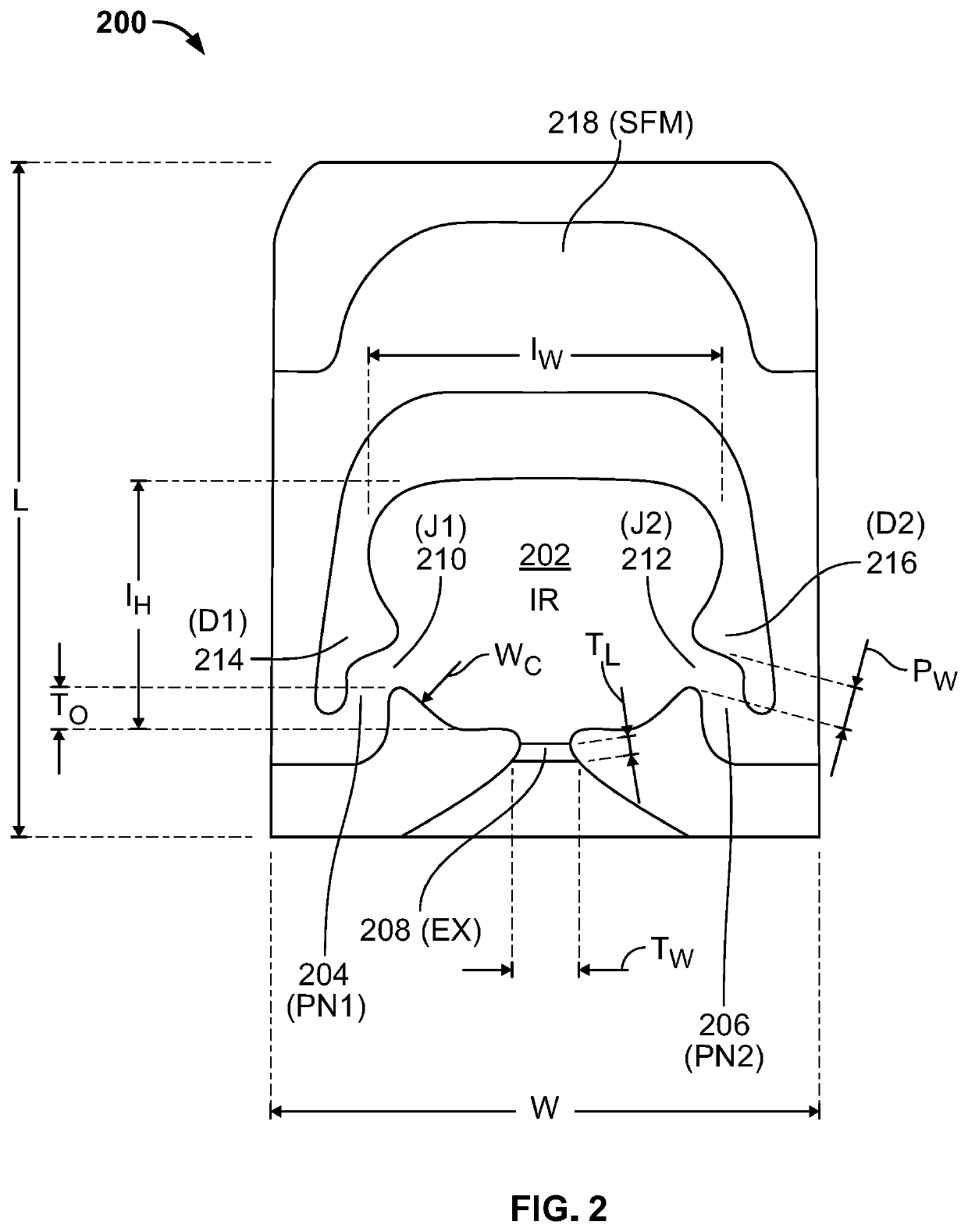
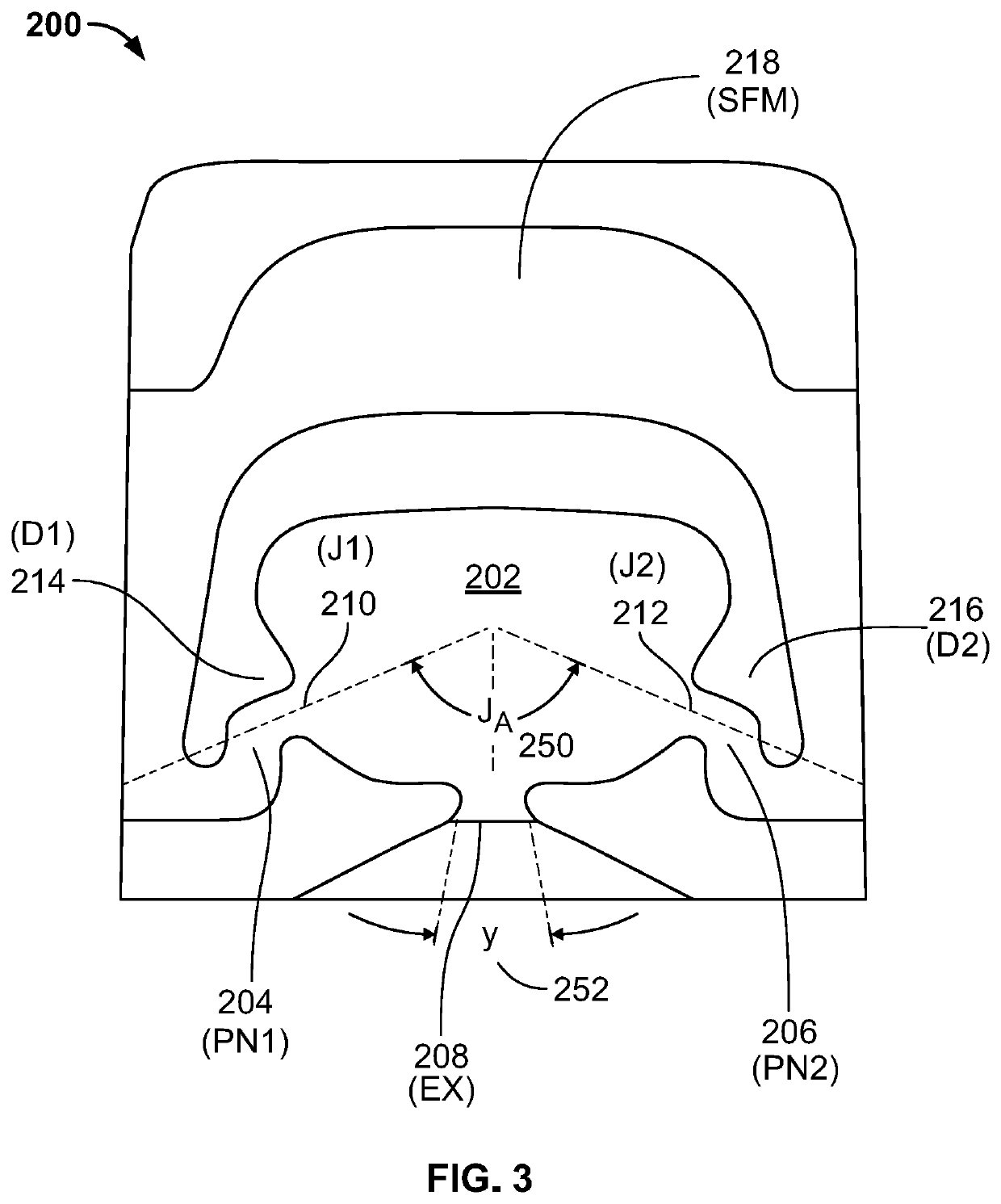
[0020]The compact fluidic nozzle assembly, and the one or more fluidic nozzle inserts located therein, of the present invention are designed with certain features that improve performance in both the spray distribution and in high viscosity conditions. The interaction region (“IR”) of the fluidic nozzle insert is important to minimizing the amount of unwanted yaw and roll that is seen in the spray profile resulting from the smaller size of the compact fluidic nozzle. In Applicants' prior work, the interaction region is dome-shaped (see FIG. 1, which illustrates features described and illustrated further in Applicants' commonly owned U.S. Pat. No. 6,253,782) while the current invention typically is designed to work with a flat-top interaction region. The flattop interaction region provides a larger corner region for the vortices to form and, as a result, the oscillating jet produces a more desirable spray fan. The power nozzle angle, or jet angle, determines the location of where the two jets from intersect, JA (see FIG. 3).
[0021]Applicants have found through development and testing of prototypes, that the best performing configuration or fluidic geometry has a jet intersect angle (JA) to be in the range of 100° to 150° to attain the desired spray fan and minimize the amount of yaw that occurs. Also, where applicants' prior fluidic geometries included a horizontal rectilinear (e.g., straight transverse) throat wall, the recent development work for the present invention includes the discovery that a concave or curvilinear wall segment provides better performance.

Problems solved by technology

Usually a fluidic nozzle insert is limited by a minimum size requirement to successfully generate fluidic oscillations, which in turn produces a spray.
One of the biggest drawbacks or performance issues that applicants see in compact fluidic nozzle assemblies is that there is significant instability, collapsing fan, yaw, roll, and significant decrease in high viscosity performance.
A major cause of this issue is the small fluidic geometry and low flow rate, both of which produce low Reynolds number (Re).
At low Re, fluidic oscillations are harder to initiate, maintain and are also unstable.

Method used


Image

  • Compact low flow rate fluidic nozzle for spraying and cleaning applications having a reverse mushroom insert geometry
  • Compact low flow rate fluidic nozzle for spraying and cleaning applications having a reverse mushroom insert geometry
  • Compact low flow rate fluidic nozzle for spraying and cleaning applications having a reverse mushroom insert geometry

Examples


Embodiment Construction

[0032]The invention relates to various low flow rate fluidic nozzle inserts having a reverse mushroom-shaped mushroom insert geometry that are useful for a wide range of spraying and cleaning applications. In one embodiment, the present invention relates to fluidic nozzle inserts that are able to perform at low flow rates with geometrical and dimensional limitations. In still another embodiment, the present invention relates to compact fluidic nozzle inserts that provide a manner by which to attain a desired level of performance in a fluidic nozzle assembly for small scale applications at low flow rates.

[0033]As used herein, approximating language may be applied to modify any quantitative representation that may vary without resulting in a change in the basic function to which it is related. Accordingly, a value modified by a term or terms, such as “about” and “substantially,” may not to be limited to the precise value specified, in some cases.

[0034]Referring now to FIGS. 2 through ...


PUM


Abstract

The invention relates to various low flow rate fluidic nozzle inserts having a reverse mushroom-shaped mushroom insert geometry that are useful for a wide range of spraying and cleaning applications. In one embodiment, the present invention relates to fluidic nozzle inserts that are able to perform at low flow rates with geometrical and dimensional limitations. In still another embodiment, the present invention relates to compact fluidic nozzle inserts that provide a manner by which to attain a desired level of performance in a fluidic nozzle assembly for small scale applications at low flow rates.

Description

RELATED APPLICATION DATA[0001]This US non-provisional application claims priority to U.S. provisional patent application No. 62 / 515,358 filed Jun. 5, 2017, the entire disclosure of which is incorporated herein by reference.FIELD OF THE INVENTION[0002]The invention relates to various low flow rate fluidic nozzle inserts having a reverse mushroom-shaped mushroom insert geometry that are useful for a wide range of spraying and cleaning applications. In one embodiment, the present invention relates to fluidic nozzle inserts that are able to perform at low flow rates with geometrical and dimensional limitations. In still another embodiment, the present invention relates to compact fluidic nozzle inserts that provide a manner by which to attain a desired level of performance in a fluidic nozzle assembly for small scale applications at low flow rates.BACKGROUND OF THE INVENTION[0003]The US National Highway Traffic Safety Administration (“NHTSA”) has mandated that as of 2018 all new vehicle...

Claims


Application Information

Patent Timeline
Patent Type & Authority Patents(United States)
IPC IPC(8): B05B1/00B05B1/08B60S1/52B60R1/00B60S1/56
CPCB05B1/00B05B1/08B60S1/52B60R1/00B60R2300/802B60R2300/8066B60S1/56
Inventor HAN, EDWARDGOPALAN, SHRIDHARZHAO, CHUNLING
Owner DLHBOWLES INC
Why Eureka
Try Eureka