
Optical reading device

a reading device and optical technology, applied in the field of optical reading devices, can solve the problems of delay in the output of the decoding result, take a lot of time in the code search process, etc., and achieve the effect of speeding up the code search process

Active Publication Date: 2022-04-19
KEYENCE
View PDF3 Cites 2 Cited by
  • Summary
  • Abstract
  • Description
  • Claims
  • Application Information

AI Technical Summary

Benefits of technology

The patent describes a method for quickly and accurately finding hidden codes in an image. The method involves capturing image data, calculating a characteristic amount that indicates the likelihood of the code, and then determining the code candidate area based on this characteristic amount. The decoding process is then executed to generate the final result. This approach allows for faster output timing and reduces the time required for the code search process, even if the size of the image is large.

Problems solved by technology

Further, while the pre-processing is often implemented in a dedicated circuit or a programmable logic device (PLD), the code search process and the decoding process are hardly constructed with a simple image manipulation process, and are not mountable in a dedicated circuit or PLD, and thus, are executed by a processor.
When the size of the read image becomes large, it takes a lot of time for the code search process.
That is, the code search process is a process of extracting and calculating a characteristic amount for evaluation of likelihood of a code while scanning the entire image, and thus, it takes time for scanning if the image size is increased, and as a result, there is a possibility that output of a decoding result may be delayed.

Method used


Image

  • Optical reading device
  • Optical reading device
  • Optical reading device

Examples


embodiment

[Function and Effect of Embodiment]

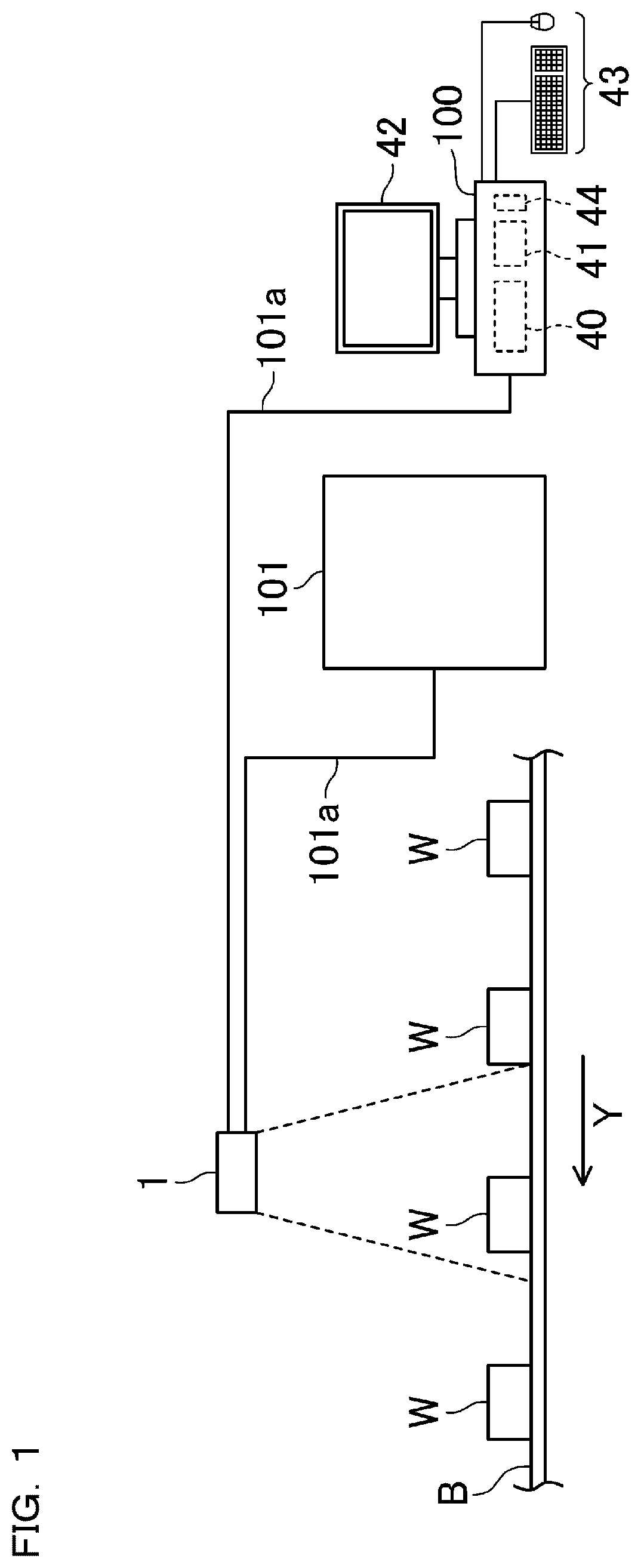
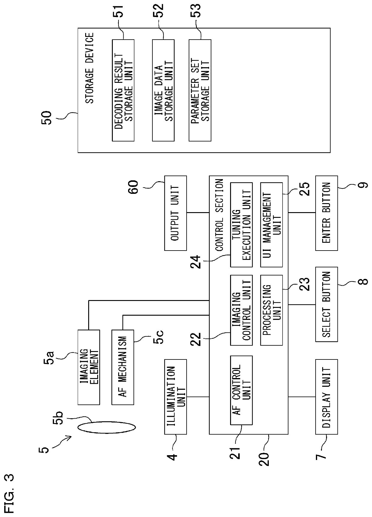
[0163]As described above, according to the present embodiment, the characteristic amount indicating the likelihood of the code is calculated while capturing the image data for each line from the imaging unit 5, the code candidate area is determined based on this characteristic amount, and the decoding process of the determined area is executed. Thus, it is unnecessary to wait until scanning of the entire image ends to search for the code, and it is possible to perform the capturing of the image data from the imaging unit 5, the calculation of the characteristic amount, and the determination of the code candidate area in parallel. As a result, the output timing of the decoding result can be accelerated even if the size of the read image is large.

[0164]In addition, the decoding processes can be executed simultaneously on a plurality of cores among the cores CR1 to CR8. In other words, the plurality of cores can simultaneously execute the decoding pro...


PUM


Abstract

Even if a size of a read image is large, a code search process can be speeded up to enable immediate output of a decoding result. Each time a predetermined number of lines of image data is taken, a pre-processing circuit executes pre-processing on the image data and calculates a characteristic amount indicating the likelihood of the code for each area in the image data. A processor determines a code candidate area based on the acquired characteristic amount and executes a decoding process of the determined area to generate a decoding result.

Description

CROSS-REFERENCE TO RELATED APPLICATIONS[0001]The present application claims foreign priority based on Japanese Patent Application No. 2020-049425, filed Mar. 19, 2020, the contents of which are incorporated herein by reference.BACKGROUND OF THE INVENTION1. Field of the Invention[0002]The present aspect relates to an optical reading device that reads information included in a read image generated by capturing an image of a workpiece.2. Description of Related Art[0003]In general, a code reader configured to be capable of capturing an image of a code, such as a bar code and a two-dimensional code, attached to a workpiece with a camera, cutting and binarizing the code included in the obtained image by image processing, and reading information by a decoding process (see, for example, Japanese Patent Laid-Open No. 2018-136860 and Japanese Patent Laid-Open No. 2012-64178).[0004]An optical reading device in Japanese Patent Laid-Open No. 2018-136860 is configured to set an upper limit of an ...

Claims


Application Information

Patent Timeline
Patent Type & Authority Patents(United States)
IPC IPC(8): G06K7/14G06K7/10
CPCG06K7/1417G06K7/10564G06K7/1413G06K7/10722G06K7/10435
Inventor YAMADA, IKUO
Owner KEYENCE
Learn More