
Pneumatic tyre

a pneumatic tyre and tread technology, applied in the field of tires, can solve the problems of affecting steering stability performance, increasing the weight of the tyre, and increasing the rolling resistance, so as to improve the rolling resistance, increase the weight of the tyre, and affect the effect of fuel economy performan

Active Publication Date: 2022-04-26
SUMITOMO RUBBER IND LTD
View PDF9 Cites 0 Cited by
  • Summary
  • Abstract
  • Description
  • Claims
  • Application Information

AI Technical Summary

Benefits of technology

[0004]However, when the thickness of the tread rubber is increased, the weight of the tyre is increased and rolling resistance is also increased, therefore, it is possible that the fuel economy performance is affected. Further, when the rigidity of the belt layer is suppressed, it is possible that the steering stability performance is affected.
[0006]The present invention was made in view of the above, and a primary object thereof is to provide a tyre having the steering stability performance, the ride comfort performance, and the noise performance achieved at a high level at the same time without deteriorating the fuel economy performance.

Problems solved by technology

However, when the thickness of the tread rubber is increased, the weight of the tyre is increased and rolling resistance is also increased, therefore, it is possible that the fuel economy performance is affected.
Further, when the rigidity of the belt layer is suppressed, it is possible that the steering stability performance is affected.
Even in the technology disclosed in the Patent Literature 1, it is not easy to achieve the steering stability performance, the ride comfort performance, the noise performance, and the fuel economy performance at the same time at a high level, there still is a demand for further improvement.

Method used


Image

  • Pneumatic tyre
  • Pneumatic tyre
  • Pneumatic tyre

Examples


working example (example)

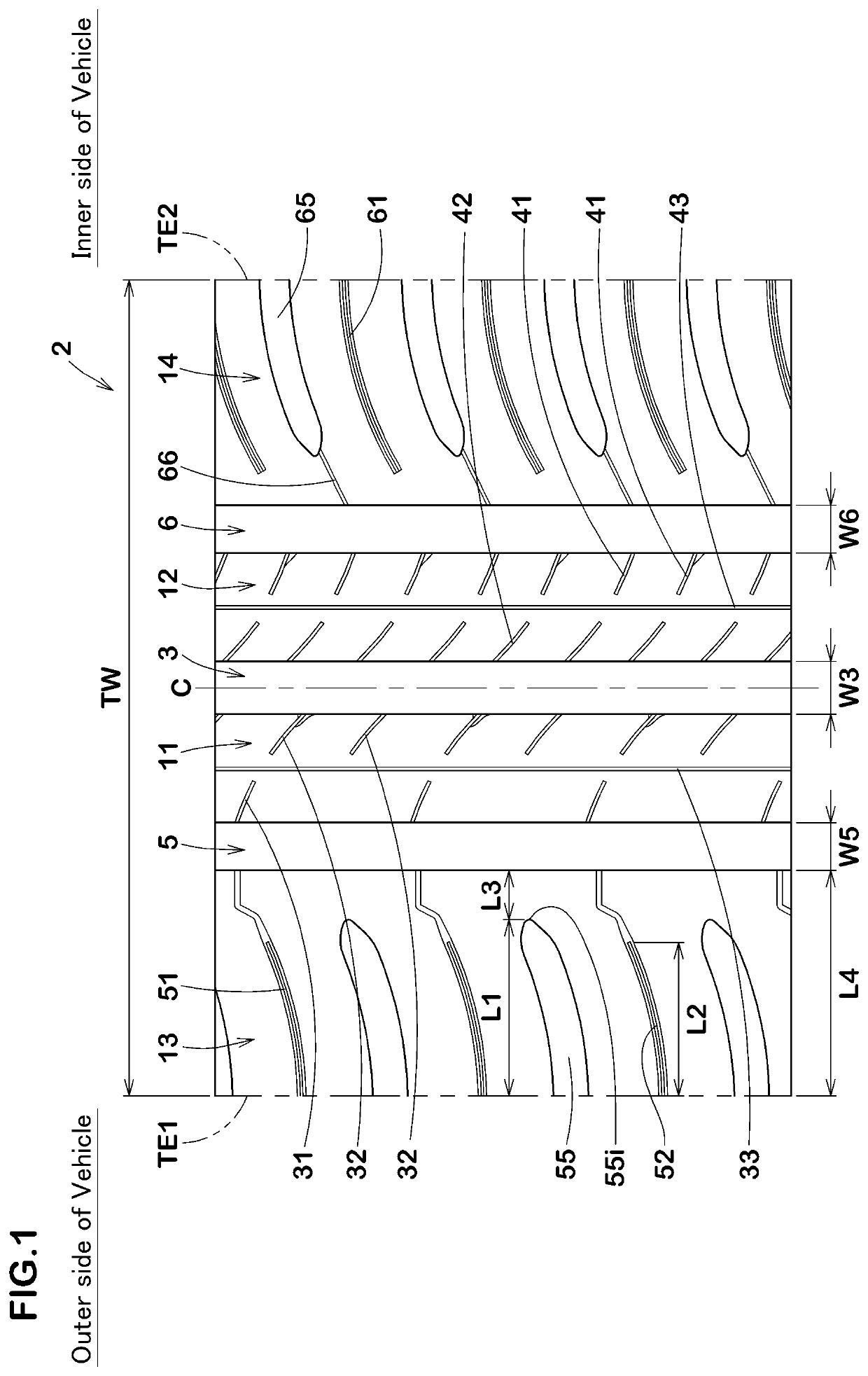
[0120]Pneumatic tyres of size 205 / 60R17 having the basic tread pattern shown in FIG. 1 were made by way of test according to the specifications listed in Table 1, and then the test tyres were tested for the drainage performance, the noise performance, and the steering stability performance.

[0121]The common specifications were as follows.

[0122]Thickness of tread rubber of crown portion: 10.0 mm

[0123]Belt cord: 1×2 / 0.295 / 46e

[0124]Belt angle: 26 degrees

[0125]Band cord: 940 dtex / 2 / 48e

[0126]Band angle: 0 degrees

[0127]The test methods were as follows.

[0128]

[0129]Each of the test tyres was mounted on a rim of 17×6.03 and mounted on all wheels of a test vehicle (FF passenger car with displacement of 1500 cc) under the condition of the tyre inner pressure of 240 kPa. While the test vehicle described above was driven on a dry asphalt road surface of a test course with the driver being the only member on the test vehicle, characteristics relating to grip performance, steering response, and res...


PUM


Abstract

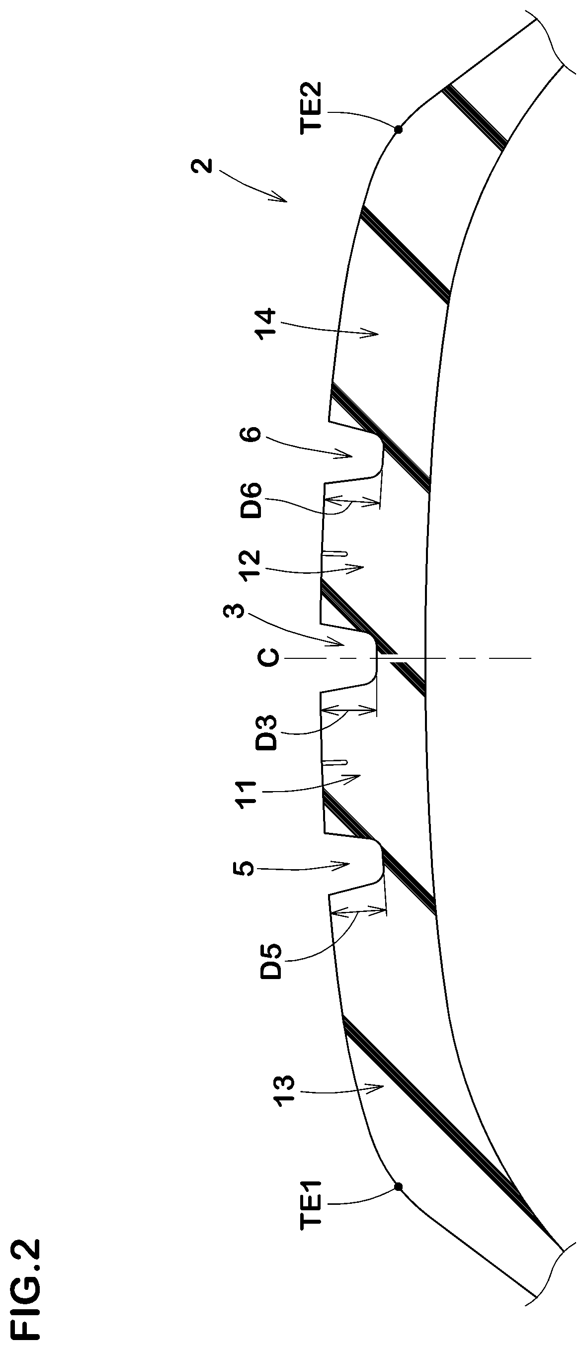
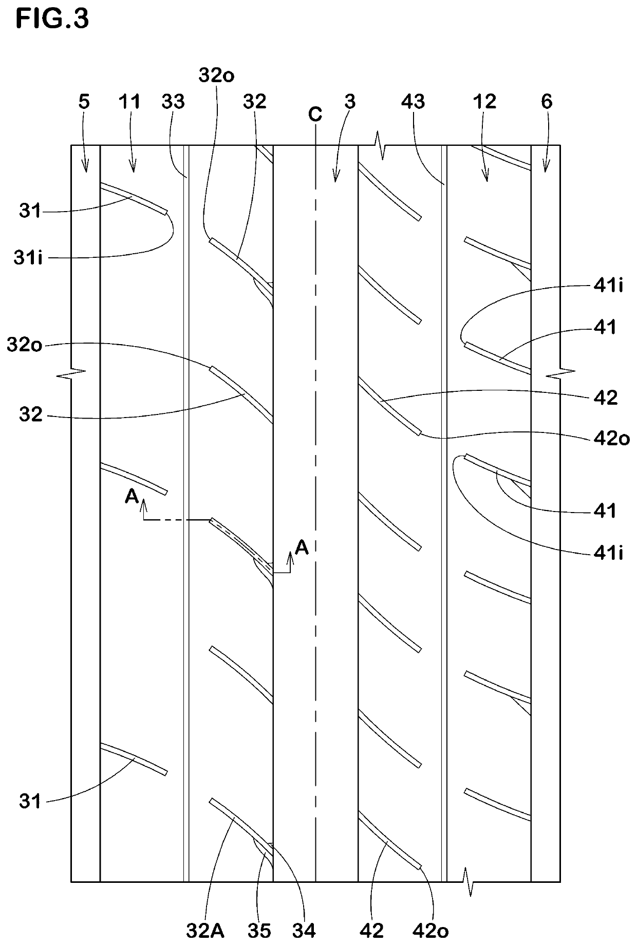
A tyre includes a tread portion having an outer shoulder main groove, a crown main groove, and an outer middle land region defined between the outer shoulder main groove and the crown main groove. The outer middle land region is provided with first middle sipes each extending inwardly in a tyre axial direction from the outer shoulder main groove to have an inner end in the outer middle land region and second middle sipes each extending outwardly in the tyre axial direction from the crown main groove to have an outer end in the outer middle land region. The number of the second middle sipes is larger than the number of the first middle sipes.

Description

TECHNICAL FIELD[0001]The present invention relates to a tyre having improved steering stability performance, ride comfort performance, noise performance, and fuel economy performance.BACKGROUND ART[0002]There has been proposed a tyre developed to have the improved noise performance while maintaining the steering stability performance (see Japanese Unexamined Patent Application Publication No. 2016-199118 (Patent Literature 1), for example).[0003]Generally speaking, in order to improve the noise performance and the ride comfort performance of a tyre, it is considered effective to decrease impact received from a road surface by increasing thickness of a tread rubber, or by suppressing rigidity of a belt layer and a band layer arranged on an outer side in a tyre radial direction thereof.SUMMARY OF THE INVENTION[0004]However, when the thickness of the tread rubber is increased, the weight of the tyre is increased and rolling resistance is also increased, therefore, it is possible that t...

Claims


Application Information

Patent Timeline
Patent Type & Authority Patents(United States)
IPC IPC(8): B60C11/12B60C11/03B60C11/13
CPCB60C11/0304B60C11/0306B60C11/1204B60C11/1236B60C11/1263B60C11/1384B60C2011/0348B60C2011/0388B60C11/03B60C11/0302B60C11/0327B60C11/12B60C2011/0337B60C11/04B60C2011/0341B60C2011/039B60C2011/1209B60C2011/1254
Inventor TANABE, MAIKOKITORA, RYUTA
Owner SUMITOMO RUBBER IND LTD
Learn More