Hybrid vehicle and method of controlling hybrid vehicle

a hybrid vehicle and hybrid technology, applied in the direction of electric control, machines/engines, transportation and packaging, etc., can solve the problems of deteriorating drivability and emission, and achieve the effect of suppressing deteriorating emission and deteriorating drivability

Active Publication Date: 2022-05-10
TOYOTA JIDOSHA KK
View PDF4 Cites 0 Cited by
  • Summary
  • Abstract
  • Description
  • Claims
  • Application Information

AI Technical Summary

Benefits of technology

[0005]In the PM generating region, a large amount of particulate matters is generated due to the load of the internal combustion engine being abruptly increased during boosting by the forced induction device as described above, with the result that emission may become deteriorated. To address this, if the output of the internal combustion engine is restricted so as to simply avoid an operating point of the internal combustion engine from being included in the PM generating region, drive torque or drive force requested for the vehicle cannot be generated, with the result that deteriorated drivability of the vehicle is concerned.
[0006]The present disclosure has been made to solve the above-described problem, and has an object to suppress deteriorated emission and deteriorated drivability in a hybrid vehicle including a rotating electrical machine and an internal combustion engine having a forced induction device.

Problems solved by technology

In the PM generating region, a large amount of particulate matters is generated due to the load of the internal combustion engine being abruptly increased during boosting by the forced induction device as described above, with the result that emission may become deteriorated.
To address this, if the output of the internal combustion engine is restricted so as to simply avoid an operating point of the internal combustion engine from being included in the PM generating region, drive torque or drive force requested for the vehicle cannot be generated, with the result that deteriorated drivability of the vehicle is concerned.

Method used


Image

  • Hybrid vehicle and method of controlling hybrid vehicle
  • Hybrid vehicle and method of controlling hybrid vehicle
  • Hybrid vehicle and method of controlling hybrid vehicle

Examples


modification 1

[0103]The above description is directed to an example in which controller 11 according to the present embodiment selects one of optimum operating line L1 and PM suppression operating line L4 in accordance with whether or not sufficient assistance by second MG 15 is obtained, and controls engine 13 using the selected operating line.

[0104]However, engine 13 may be controlled only using optimum operating line L1 without using PM suppression operating line L4.

[0105]FIG. 8 is a flowchart showing exemplary processing performed by HV-ECU 62 according to the present modification. This flowchart is obtained by removing the processing of steps S40 and S70 from the flowchart shown in FIG. 7. That is, when it is determined that there is a request for activation of engine 13 (YES in step S20), HV-ECU 62 sets the target engine operating point using optimum operating line L1 irrespective of whether or not sufficient assistance by second MG 15 is obtained (step S50). When the target engine operatin...

modification 2

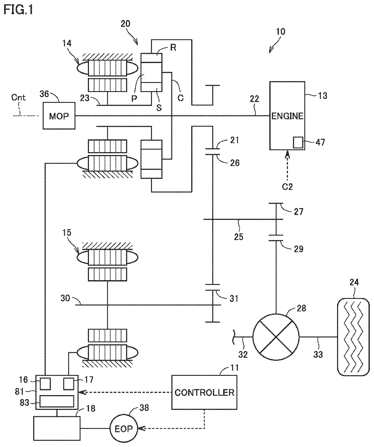
[0107]Although vehicle 10 shown in FIG. 1 is a type (so-called split type) of hybrid vehicle including engine 13 and two MGs 14 and 15 as drive sources, a vehicle to which the control according to the present disclosure is applicable is not limited to vehicle 1 shown in FIG. 1. For example, the control according to the present disclosure is applicable to a general series or parallel type hybrid vehicle including an engine and one MG.


PUM


Abstract

A vehicle includes: a motor generator; an engine having a forced induction device; and a HV-ECU. An operation region of the engine includes a PM generating region in which an amount of particulate matters included in exhaust gas of the engine is more than a predetermined amount due to a load of the engine being abruptly increased during boosting by the forced induction device. The PM generating region is a low-rotation and high-torque region. When assistance by the motor generator is sufficiently obtained and the engine is operated in the PM generating region, the HV-ECU restricts an increasing rate of the torque of the engine to be less than or equal to an upper limit rate. The HV-ECU complements, by the torque of the motor generator, the torque of the engine restricted by restricting the increasing rate of the torque of the engine.

Description

[0001]This nonprovisional application is based on Japanese Patent Application No. 2019-077718 filed on Apr. 16, 2019, with the Japan Patent Office, the entire contents of which are hereby incorporated by reference.BACKGROUNDField[0002]The present disclosure relates to: a hybrid vehicle including, as drive sources, a rotating electrical machine and an internal combustion engine having a forced induction device; and control thereof.Description of the Background Art[0003]Conventionally, a hybrid vehicle has been known which includes, as drive sources, a rotating electrical machine and an internal combustion engine having a forced induction device (for example, see Japanese Patent Laying-Open No. 2015-58924).SUMMARY[0004]It has been known that an operation region of such an internal combustion engine having a forced induction device includes a specific region in which an amount of particulate matters (PM) included in exhaust gas of the internal combustion engine is more than a predeterm...

Claims


Application Information

Patent Timeline
Patent Type & Authority Patents(United States)
IPC IPC(8): B60W20/15B60W10/06B60W10/08F02D41/02
CPCB60W20/15B60W10/06B60W10/08F02D41/0235B60W2510/0638B60W2510/0657B60W2710/0666B60W2710/083B60W20/16B60W30/1882F02D29/02F02D2250/26F02D2250/38F02D2250/18Y02T10/72B60K6/445Y02T10/62
Inventor YONEZAWA, KOICHIYOSHIZAKI, SATOSHIMAEDA, OSAMUANDO, DAIGOASAMI, YOSHIKAZUITAGAKI, KENJIOYAMA, SHUNSUKEMUTA, KOICHIRO
Owner TOYOTA JIDOSHA KK
Why Eureka
Try Eureka