
Control apparatus for vehicular automatic transmission

a technology of automatic transmission and control apparatus, which is applied in the direction of electric propulsion mounting, dynamo-electric gear control, road transportation, etc., can solve the problems of deterioration of vehicle drivability risk, and achieve the effect of effective reduction of deterioration of vehicle drivability during the operation of brake operating member, and sweeping ra

Active Publication Date: 2011-11-29
TOYOTA JIDOSHA KK
View PDF12 Cites 7 Cited by
  • Summary
  • Abstract
  • Description
  • Claims
  • Application Information

AI Technical Summary

Benefits of technology

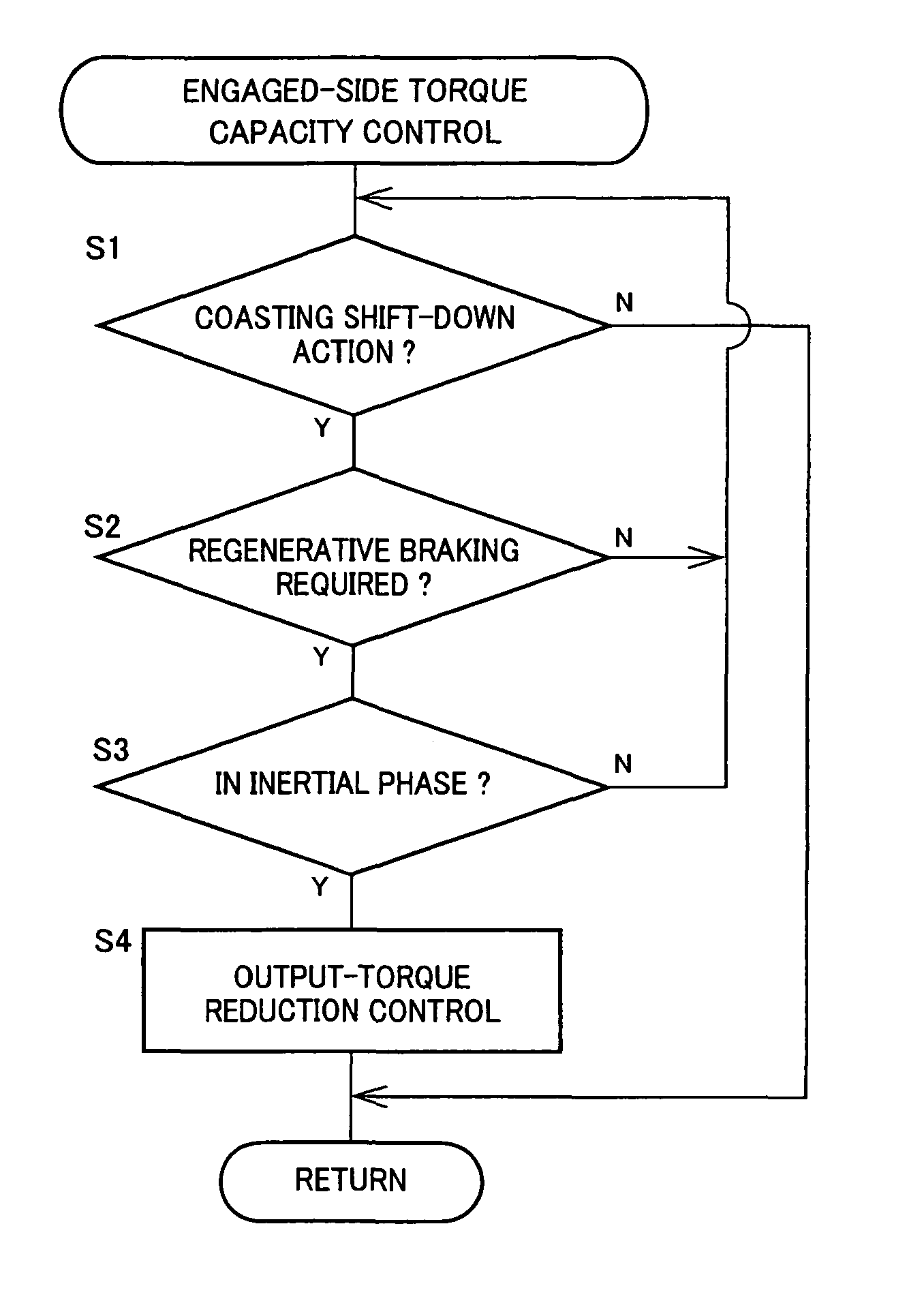
[0008]The vehicle including the automatic transmission for which the present control apparatus is provided has the transmission portion constituting a part of the power transmitting path between the engine and the drive wheel, and the electric motor operatively connected to an element of the transmission portion. The control apparatus is configured to generate the regenerative braking command commanding the electric motor to generate the predetermined regenerative braking force when the brake operating member is operated, and to implement the sweep control of the torque capacity of the coupling element of the transmission portion when the coupling element is engaged to perform a shifting action of the transmission portion. The control apparatus is further configured to increase the sweeping rate in the sweep control of the torque capacity of the coupling element of the transmission portion to be engaged to perform the shifting action, when the regenerative braking command is generated during the inertia phase of the shifting action, so that the coupling element is rapidly engaged for the purpose of generating an engine braking force when the regenerative braking command is generated according to the operation of the brake operating member during the inertia phase of the shifting action. Accordingly, the braking force generated during the shifting action is equal to the braking force generated in the normal state (in the absence of the shifting action). Namely, the present control apparatus for the vehicular automatic transmission permits effective reduction of deterioration of the vehicle drivability upon operation of the brake operating member.
[0009]Preferably, an amount of increase of the sweeping rate in the sweep control is determined such that a deceleration value of the vehicle corresponding to an amount of operation of the brake operating member during the shifting action of the transmission portion is equivalent to a deceleration value of the vehicle corresponding to the amount of operation of the brake operating member while the transmission portion is not in the shifting action. It is also preferable that an amount of increase of the sweeping rate in the sweep control is determined on the basis of an input torque of the transmission portion and according to a predetermined relationship between the amount of increase and the input torque. In this case, the deterioration of the vehicle drivability during the operation of the brake operating member can be effectively reduced.
[0010]It is also preferable that the sweeping rate is increased in the sweep control during a clutch-to-clutch shifting action of the transmission portion, which is performed by a releasing action of a coupling device of the transmission portion and an engaging action of the coupling device of the transmission portion to be engaged. In this case, the deterioration of the vehicle drivability upon operation of the brake operating member can be suitably reduced during the clutch-to-clutch shifting action in which the output torque of the transmission portion tends to be reduced. It is also preferable that the sweeping rate is increased in the sweep control during a coasting shift-down action of the transmission portion from a comparatively high gear position to a comparatively low gear position while an accelerator pedal is placed in a non-operated position. In this case, the deterioration of the vehicle drivability upon operation of the brake operating member can be suitably reduced during the coasting shift-down action in which the vehicle drivability tends to be deteriorated.

Problems solved by technology

However, the vehicle not employing the above-described electronic control brake and arranged to control the electric motor to generate the predetermined amount of regenerative braking force upon operation of the brake operating member has a risk of deterioration of its drivability due to a failure to produce a required total braking force if the brake pedal is operated during a shifting action of the transmission portion.

Method used


Image

  • Control apparatus for vehicular automatic transmission
  • Control apparatus for vehicular automatic transmission
  • Control apparatus for vehicular automatic transmission

Examples


embodiment

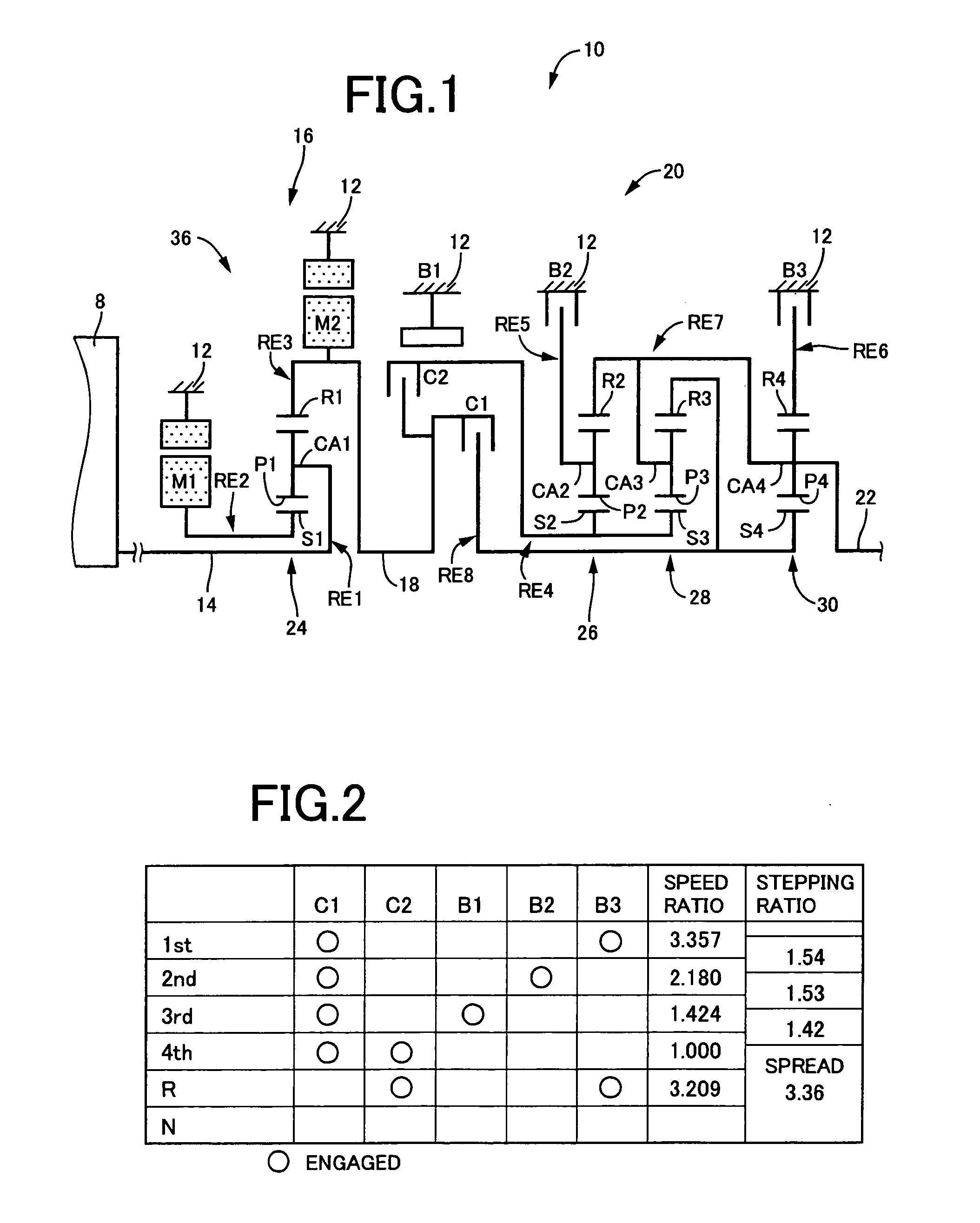
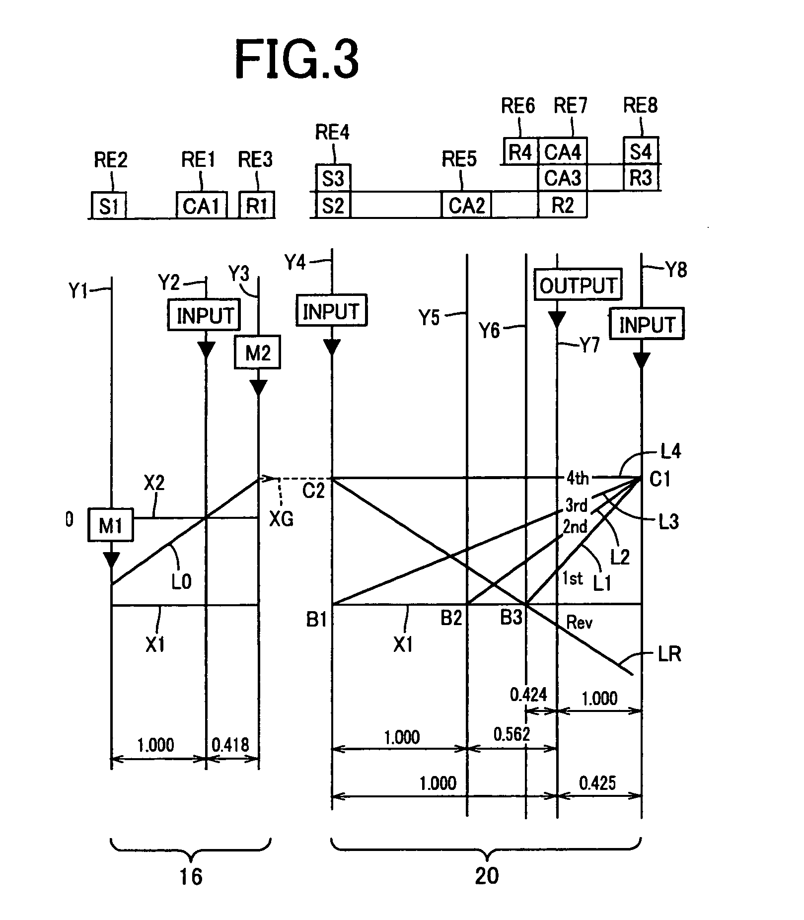
[0031]FIG. 1 is the schematic view showing the arrangement of a vehicular power transmitting system 10 to which the present invention is applicable. The power transmitting system 10 is longitudinally installed on an FR (front-engine rear-drive) vehicle, for example, and includes: an input shaft 14; a differential portion 16 connected to the input shaft 14 either directly, or indirectly via a pulsation absorbing damper (vibration damping device) not shown; an automatic transmission portion 20 disposed between the differential portion 16 and drive wheels 34 (shown in FIG. 6) and connected in series via a power transmitting member 18 (power transmitting shaft) to the differential portion 16; and an output shaft 22 connected to the automatic transmission portion 20. The input shaft 12, differential portion 16, automatic transmission portion 20 and output shaft 22 are coaxially disposed on a common axis in a transmission casing 12 (hereinafter referred to simply as “casing 12”) functioni...


PUM


Abstract

A control apparatus for a vehicular automatic transmission, which permits effective reduction of deterioration of vehicle drivability upon operation of a brake operating member, and which is configured to increase a sweeping rate in a sweep control of the torque capacity of a coupling element of an automatic transmission portion 20 to be engaged to perform a shifting action when a regenerative braking command is generated according to the operation of the brake operating member during an inertia phase of the shifting action, so that the coupling element is rapidly engaged for the purpose of generating an engine braking force when the regenerative braking command is generated according to the operation of the brake operating member during the inertia phase of the shifting action. Accordingly, the braking force generated during the shifting action is equal to the braking force generated in the normal state (in the absence of the shifting action).

Description

TECHNICAL FIELD[0001]The present invention relates to a control apparatus for a vehicular automatic transmission, and more particularly to an improvement for reducing deterioration of vehicle drivability upon vehicle braking.BACKGROUND ARTField of the Invention[0002]There is known a control apparatus for an automatic transmission of a vehicle having a transmission portion constituting a part of a power transmitting path between an engine and a drive wheel, and an electric motor operatively connected to an element of the transmission portion. Patent document 1 discloses an example of such a control apparatus for a hybrid drive system. This type of control apparatus is generally configured to implement a sweep control of a transmission upon a shifting action of the transmission, for reducing deterioration of drivability of the vehicle due to a shifting shock of the transmission. In the sweep control, the torque capacity of a coupling element of the transmission to be released to perfo...

Claims


Application Information

Patent Timeline
Patent Type & Authority Patents(United States)
IPC IPC(8): H02P17/00B60W10/00B60K6/445B60K6/547B60L7/14B60L15/20B60L50/16B60W10/08B60W10/10B60W10/18B60W20/00F16H59/14F16H59/18F16H59/48F16H59/54F16H59/68F16H61/02F16H61/06F16H61/68F16H61/684F16H61/686
CPCB60W30/18136F16H61/0437F16H61/686B60K6/445Y10T477/26B60W10/08B60W10/115B60W20/00B60W2510/1015B60W2510/104B60W2540/10B60W2540/12Y02T10/52Y02T10/6239Y02T10/7258Y10T477/23Y10S903/945Y10S903/947Y10T477/33Y10T477/647B60L2240/486Y02T10/84Y02T10/40Y02T10/62Y02T10/72Y02T10/60B60W10/10B60W2510/02B60W20/13
Inventor MINAMIKAWA, KOKI
Owner TOYOTA JIDOSHA KK
Learn More