Hybrid vehicle and method of controlling hybrid vehicle

a hybrid vehicle and hybrid technology, applied in the direction of electric control, machines/engines, transportation and packaging, etc., can solve the problems of deteriorating drivability and emission, and achieve the effect of suppressing deteriorating emission and deteriorating drivability

Active Publication Date: 2020-10-22
TOYOTA JIDOSHA KK
View PDF0 Cites 0 Cited by
  • Summary
  • Abstract
  • Description
  • Claims
  • Application Information

AI Technical Summary

Benefits of technology

[0005]In the PM generating region, a large amount of particulate matters is generated due to the load of the internal combustion engine being abruptly increased during boosting by the forced induction device as described above, with the result that emission may become deteriorated. To address this, if the output of the internal combustion engine is restricted so as to simply avoid an operating point of the internal combustion engine from being included in the PM generating region, drive torque or drive force requested for the vehicle cannot be generated, with the result that deteriorated drivability of the vehicle is concerned.
[0006]The present disclosure has been made to solve the above-described problem, and has an object to suppress deteriorated emission and deteriorated drivability in a hybrid vehicle including a rotating electrical machine and an internal combustion engine having a forced induction device.

Problems solved by technology

In the PM generating region, a large amount of particulate matters is generated due to the load of the internal combustion engine being abruptly increased during boosting by the forced induction device as described above, with the result that emission may become deteriorated.
To address this, if the output of the internal combustion engine is restricted so as to simply avoid an operating point of the internal combustion engine from being included in the PM generating region, drive torque or drive force requested for the vehicle cannot be generated, with the result that deteriorated drivability of the vehicle is concerned.

Method used


Image

  • Hybrid vehicle and method of controlling hybrid vehicle
  • Hybrid vehicle and method of controlling hybrid vehicle
  • Hybrid vehicle and method of controlling hybrid vehicle

Examples


Embodiment Construction

[0019]The following describes embodiments of the present disclosure with reference to figures in detail. It should be noted that the same or corresponding portions in the figures are given the same reference characters and are not described repeatedly.

[0020]

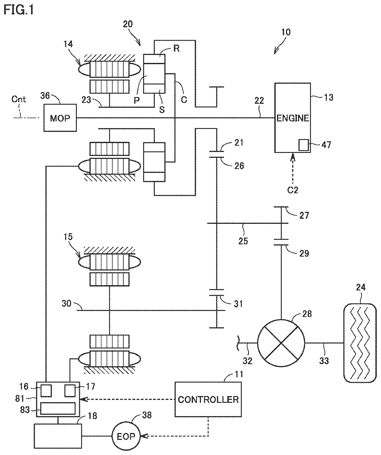
[0021]FIG. 1 is a diagram showing an exemplary configuration of a drive system of a hybrid vehicle (hereinafter, also simply referred to as “vehicle”) 10. As shown in FIG. 1, as drive sources for running, vehicle 10 includes: an engine (internal combustion engine) 13; and a second motor generator (rotating electrical machine, which is hereinafter also referred to as “second MG”) 15. Vehicle 10 further includes a controller 11 and a first motor generator (hereinafter, also referred to as “first MG”) 14.

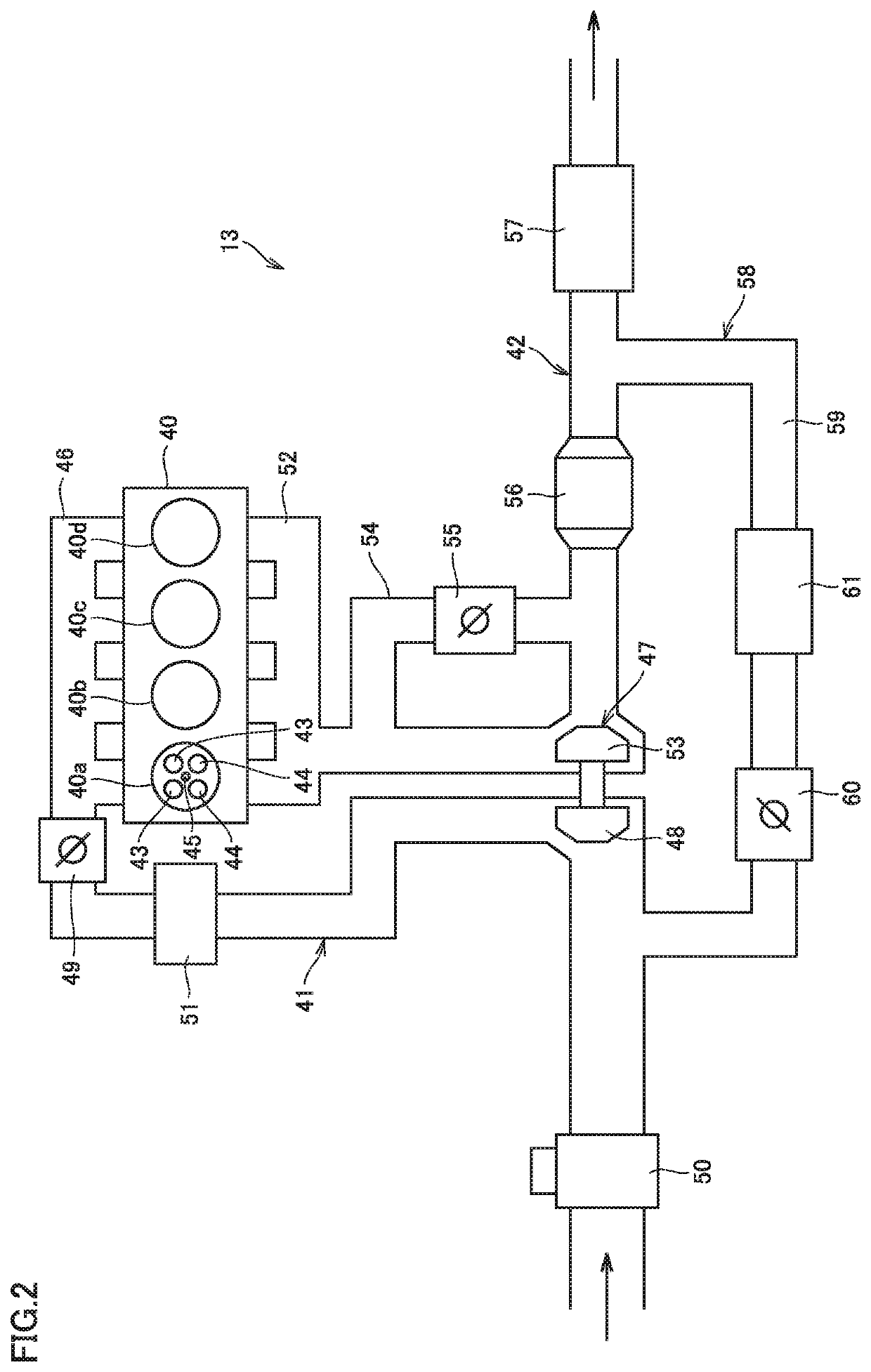
[0022]Engine 13 has a forced induction device (turbocharger) 47. First MG 14 and second MG 15 each have a function as a motor that outputs torque by being supplied with driving electric power and have a function as a generator that ...


PUM


Abstract

A vehicle includes: a motor generator; an engine having a forced induction device; and a HV-ECU. An operation region of the engine includes a PM generating region in which an amount of particulate matters included in exhaust gas of the engine is more than a predetermined amount due to a load of the engine being abruptly increased during boosting by the forced induction device. The PM generating region is a low-rotation and high-torque region. When assistance by the motor generator is sufficiently obtained and the engine is operated in the PM generating region, the HV-ECU restricts an increasing rate of the torque of the engine to be less than or equal to an upper limit rate. The HV-ECU complements, by the torque of the motor generator, the torque of the engine restricted by restricting the increasing rate of the torque of the engine.

Description

[0001]This nonprovisional application is based on Japanese Patent Application No. 2019-077718 filed on Apr. 16, 2019, with the Japan Patent Office, the entire contents of which are hereby incorporated by reference.BACKGROUNDField[0002]The present disclosure relates to: a hybrid vehicle including, as drive sources, a rotating electrical machine and an internal combustion engine having a forced induction device; and control thereof.Description of the Background Art[0003]Conventionally, a hybrid vehicle has been known which includes, as drive sources, a rotating electrical machine and an internal combustion engine having a forced induction device (for example, see Japanese Patent Laying-Open No. 2015-58924).SUMMARY[0004]It has been known that an operation region of such an internal combustion engine having a forced induction device includes a specific region in which an amount of particulate matters (PM) included in exhaust gas of the internal combustion engine is more than a predeterm...

Claims


Application Information

Patent Timeline
Patent Type & Authority Applications(United States)
IPC IPC(8): B60W20/15B60W10/06B60W10/08F02D41/02
CPCB60W2510/0657B60W10/06B60W20/15B60W2510/0638F02D41/0235B60W10/08B60W2710/0666B60W2710/083B60W20/16B60W30/1882F02D29/02F02D2250/26F02D2250/38F02D2250/18Y02T10/72B60K6/445Y02T10/62
Inventor YONEZAWA, KOICHIYOSHIZAKI, SATOSHIMAEDA, OSAMUANDO, DAIGOASAMI, YOSHIKAZUITAGAKI, KENJIOYAMA, SHUNSUKEMUTA, KOICHIRO
Owner TOYOTA JIDOSHA KK
Why Eureka
Try Eureka