Power-saving door lock systems and methods

a door lock and electronic technology, applied in the field of electronic door lock systems, can solve problems such as the battery life of such connected door locks, and achieve the effect of saving battery li

Active Publication Date: 2022-05-17
HAMPTON PRODS INT
View PDF7 Cites 0 Cited by
  • Summary
  • Abstract
  • Description
  • Claims
  • Application Information

AI Technical Summary

Benefits of technology

[0006]In one embodiment, a system could be programmed to switch the transceiver to sleep mode when a motion sensor stops detecting movement or after a period of time when the motion sensor detects that no entities are in a defined area, and switches the transceiver to an active mode when the motion sensor detects that an entity is in the defined area—minimizing the amount of power the transceiver drains. When the transceiver is in the active mode, the transceiver can then contact a server via a network and download door lock instructions from the server to execute those door lock execution instructions on the door lock apparatus after a network session has been established. After a predetermined time period with no activity on the lock including no detection of motion within the defined area, the transceiver can return to the sleep mode.
[0008]In another embodiment, a system clock allows instructions to execute only when a threshold time value has been reached. In such an embodiment, instructions could time-out, or could only be triggered within a time period, or after a threshold time value. In some embodiments, instructions could be deactivated or deleted from a memory when the system clock hits a threshold time period value, or the instructions could be stored on the server, but could be deleted from the server when a threshold time period value has been reached. Such an embodiment prevents legacy instructions from taking up valuable space in memory if the instructions no longer need to be executed since the system has detected that a threshold time value can no longer be reached.

Problems solved by technology

Battery life on such connected door locks becomes an issue with power hungry components.

Method used


Image

  • Power-saving door lock systems and methods
  • Power-saving door lock systems and methods
  • Power-saving door lock systems and methods

Examples


Embodiment Construction

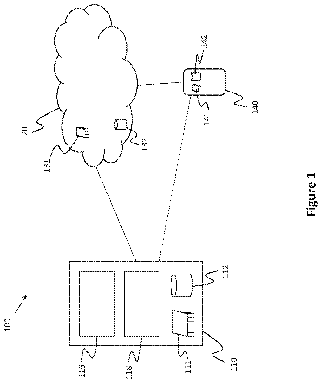
[0018]Referring to FIG. 1, an embodiment of a door lock system 100 comprises a door lock 110, a server 120, and a remote computer system 140.

[0019]As used herein, a “computer system” comprises any suitable combination of computing or compute devices, such as desktops, laptops, cellular phones, blades, servers, interfaces, systems, databases, agents, peers, engines, modules, or controllers, operating individually or collectively. Computer systems and servers may comprise at least a processor configured to execute software instructions stored on a tangible, non-transitory computer readable storage medium (e.g., hard drive, solid state drive, RAM, flash, ROM, etc.). The software instructions preferably configure the computer system and server to execute the functionality as disclosed. Thus, each of door lock 110, remote server 120, and / or remote computer system 140 could comprise a plurality of distributed computer systems. Remote server 120 is preferably embodied on a network of one o...


PUM


Abstract

An electronic door lock system that saves power by putting some electronic devices, such as transceivers, in sleep mode and by executing instructions only in response to ambient trigger scenarios. Instructions sent to an electronic door lock from a remote device could be stored on a server before being downloaded to the electronic door lock system once the transceiver is awakened from sleep mode.

Description

BACKGROUND OF THE INVENTION[0001]This invention relates generally to electronic door locks, and more particularly, to electronic door locks connected to a network.[0002]Some electronic door locks typically have a key tumbler and a keypad as alternative means to lock and unlock the door. Some door locks can also connect to a network which allows a mobile device to communicate with and control the door lock. Battery life on such connected door locks becomes an issue with power hungry components.BRIEF SUMMARY OF THE INVENTION[0003]Aspects of the invention are in the technical field of electronic door lock systems. More particularly, aspects of the invention relate to the technical field of power-saving electronic door lock systems.[0004]Door lock execution instructions may be sent from a remote computer system, such as a desktop computing device or a handheld computing device (e.g., laptop, cellular phone, remote device), to an electronic door lock via a network. The electronic door lo...

Claims


Application Information

Patent Timeline
Patent Type & Authority Patents(United States)
IPC IPC(8): G07C9/00E05B47/06E05B47/00G07C9/37
CPCG07C9/00857E05B47/0002E05B47/0603G07C9/0069G07C9/00182G07C9/00563G07C9/37G07C9/00571G07C9/00309G07C2009/00365G07C2209/64E05B2047/0065E05B47/0012E05B47/026E05B2047/0084E05B2047/0064
Inventor KELLEY, KIMQUAN, JON FONGSHEN, HOWARD
Owner HAMPTON PRODS INT
Why Eureka
Try Eureka