Method and apparatus for discharging a lifting magnet

a technology of lifting magnets and ac capacitors, which is applied in the direction of magnetic bodies, load-engaging elements, electromagnetic relay details, etc., can solve the problems of prohibitively high price, bulky, and high cost of ac capacitors of more than a few tens of microfarads with a sufficient voltage rating, so as to reduce current, prevent damage to semiconductor switching elements, and high voltage

Inactive Publication Date: 2013-01-08
WEED MICHAEL ALLEN
View PDF7 Cites 0 Cited by
  • Summary
  • Abstract
  • Description
  • Claims
  • Application Information

AI Technical Summary

Benefits of technology

[0018]The present invention approximates the ideal discharge impedance in a stepwise fashion that still discharges the magnet fast enough, avoids a high voltage transient and is inexpensive. Two flyback diodes are connected across the magnet in opposite directions via switches. The switches can be semiconductors such as field effect transistors (FETs), insulated gate bipolar transistors (IGBTs) or the like. Since they are used as switches (either “on” or “off”), these devices do not need to handle a large amount of power. When “off”, there is no current through the device, hence no power is dissipated. When “on”, there is little voltage across the device, and again little power is dissipated. During the lift phase, one diode is switched across the magnet in the reverse-biased direction, so it does not conduct, and the other diode is switched out of the circuit. When the lift voltage is removed, the diode that is connected across the magnet becomes forward-biased to the current sourced by the magnet, and discharges the magnet at a low voltage. When the magnet is sufficiently discharged, the lift phase diode is switched out of the circuit, the reverse phase diode is switched in and the reverse voltage is applied. This diode remains in the circuit for some time after the reverse voltage is removed, thereby discharging the magnet after the reverse phase.
[0019]This method dissipates most of the stored magnetic energy in the magnet itself during discharge. Magnets are designed to dissipate this amount of power, so there is little additional cost associated with this method. A capacitor is permanently connected across the magnet which prevents a high voltage transient when the discharge diodes are disconnected. The capacitor briefly accumulates charge from the small amount of remaining discharge current, then this charge flows through the magnet resistance until the capacitor is discharged. Since the capacitor is connected across the magnet, and the magnet voltage must be reversed, the capacitor must be an AC type, not polarized. AC capacitors of more than a few tens of microfarads with a sufficient voltage rating are expensive and bulky. An alternative to a single AC capacitor consisting of two polarized (DC) capacitors, four diodes and a resistor is shown that provides an effective capacitance of several hundred microfarads in this application, is inexpensive and relatively small in size.
[0021]The voltages between the various semiconductor elements are at widely different values during operation, so an isolated signal is needed to drive each switch. A standard integrated circuit that is widely available is used for this purpose in the present invention. In addition to being isolated, the switch driver must change the switch between “on” to “off” states quickly to avoid excessive power dissipation in the switching device, and must firmly hold the switching device in the “off” state to prevent inadvertent turn-on caused by extraneous signals.

Problems solved by technology

However, a transistor used to discharge an industrial lifting magnet in this manner would have to be capable of dissipating a large amount of power, and would be prohibitively expensive.
AC capacitors of more than a few tens of microfarads with a sufficient voltage rating are expensive and bulky.

Method used


Image

  • Method and apparatus for discharging a lifting magnet
  • Method and apparatus for discharging a lifting magnet
  • Method and apparatus for discharging a lifting magnet

Examples


Embodiment Construction

[0025]It is to be understood that the present disclosure is an exemplification of the principles of the invention and does not limit the invention to the illustrated embodiments.

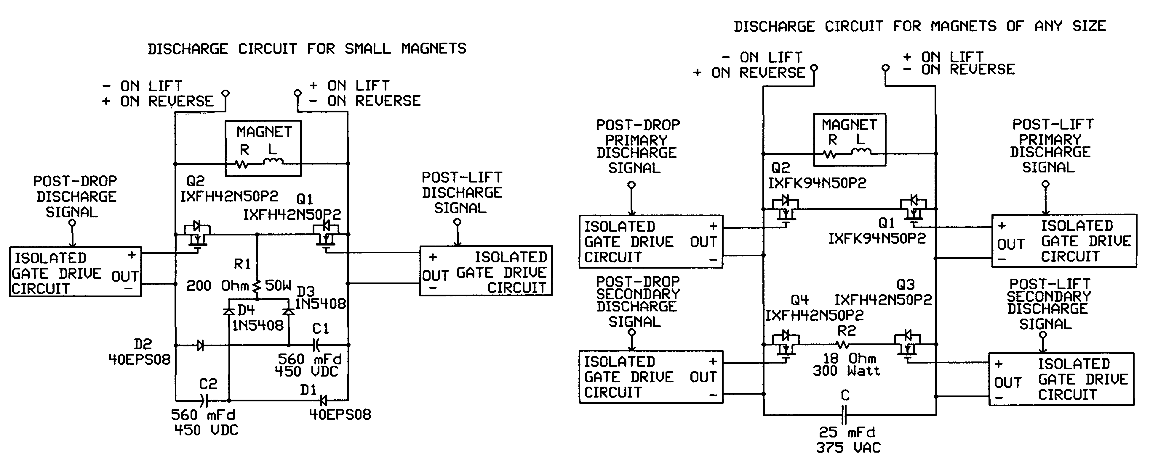
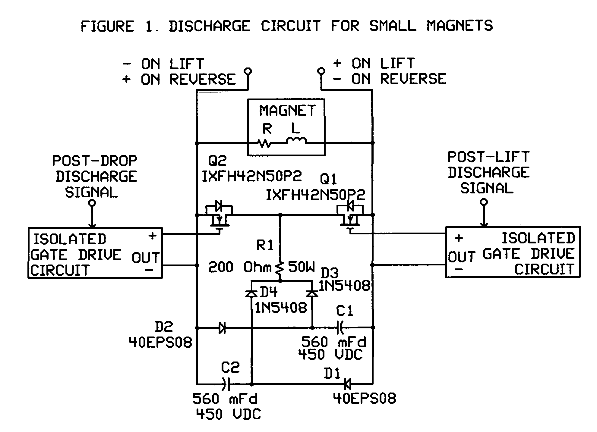
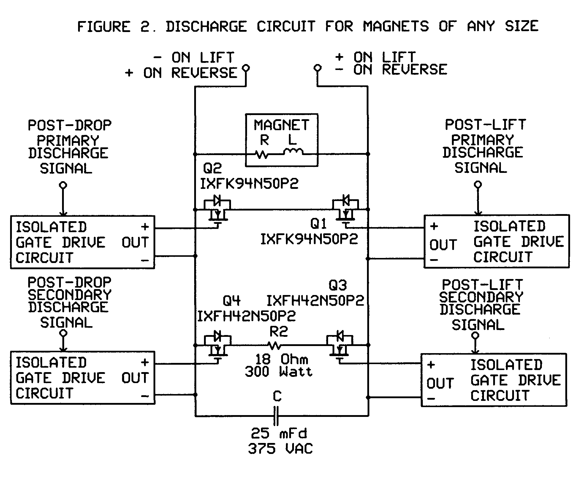
[0026]No voltage is applied to the magnet in the initial state, the magnet is fully discharged, and the switches controlling the flyback diodes are off. In the discharge circuit of FIG. 1 the capacitors C1 and C2 are fully discharged. In the discharge circuit of FIG. 2 the capacitor C3 is fully discharged and the second set of switches shown as Q3 and Q4 are off. The switches are FETs in the preferred embodiment, as shown in the drawings. The operator signals the controller for a “lift” by, for example, pressing a pushbutton. The control circuit responds by applying voltage to the magnet in the “lift” direction. Ideally, the switch controlling the “lift” flyback diode is turned on at this time. This switch is shown as Q1 in the drawings, and the flyback diode for “lift” is the body diode of Q2. The power sou...


PUM


Abstract

A method for discharging an industrial lifting magnet quickly without producing a high voltage transient is presented. Most of the stored magnetic energy is dissipated in the magnet itself by connecting a diode across the magnet in the appropriate direction at discharge time using switching devices. One variation, suitable for smaller magnets, discharges the remaining energy using DC capacitors and a diode switching network. Another variation, suitable for magnets of any size, discharges most of the remaining energy in a power resistor of modest size using a system of diodes and switching devices in conjunction with a relatively small AC capacitor across the magnet.

Description

CROSS-REFERENCE TO RELATED APPLICATIONS[0001]The previous application number was 12 / 927,863.STATEMENT REGARDING FEDERALLY SPONSORED RESEARCH OR DEVELOPMENT[0002]This invention was not made under Federally sponsored research or development.REFERENCE TO SEQUENCE LISTING, A TABLE, OR A COMPUTER LISTING COMPACT DISC APPENDIX[0003]Not applicable.BACKGROUND OF THE INVENTION[0004]A direct current (DC) or rectified alternating current (AC) is applied to an electromagnet attached by mechanical means to a boom to attract and hold ferrous metals. The magnet is then moved to another location and the current is removed from the magnet coil to release the metal. However, the magnet core is not completely demagnetized when all the current is removed, so some amount of current must be applied for some period of time in a direction opposite to the original current flow to release all the metal. This results in a “clean drop”.[0005]Originally, a mechanical contact arrangement was employed to apply an...

Claims


Application Information

Patent Timeline
Patent Type & Authority Patents(United States)
IPC IPC(8): H01H47/22H01H47/32
CPCB66C1/08H01F7/204
Inventor WEED, MICHAEL ALLEN
Owner WEED MICHAEL ALLEN
Why Eureka
Try Eureka