
Flexible bearing for compliant mechanisms

a technology of bearings and bearings, applied in the direction of pivotal connections, basic electric elements, connections, etc., can solve the problems of limited rotation angle of flexure bearings, failure of equipment, and restriction or limitation of bearing lubricants us

Active Publication Date: 2022-05-31
PRINCE MOHAMMAD BIN FAHD UNIV
View PDF10 Cites 4 Cited by
  • Summary
  • Abstract
  • Description
  • Claims
  • Application Information

AI Technical Summary

Benefits of technology

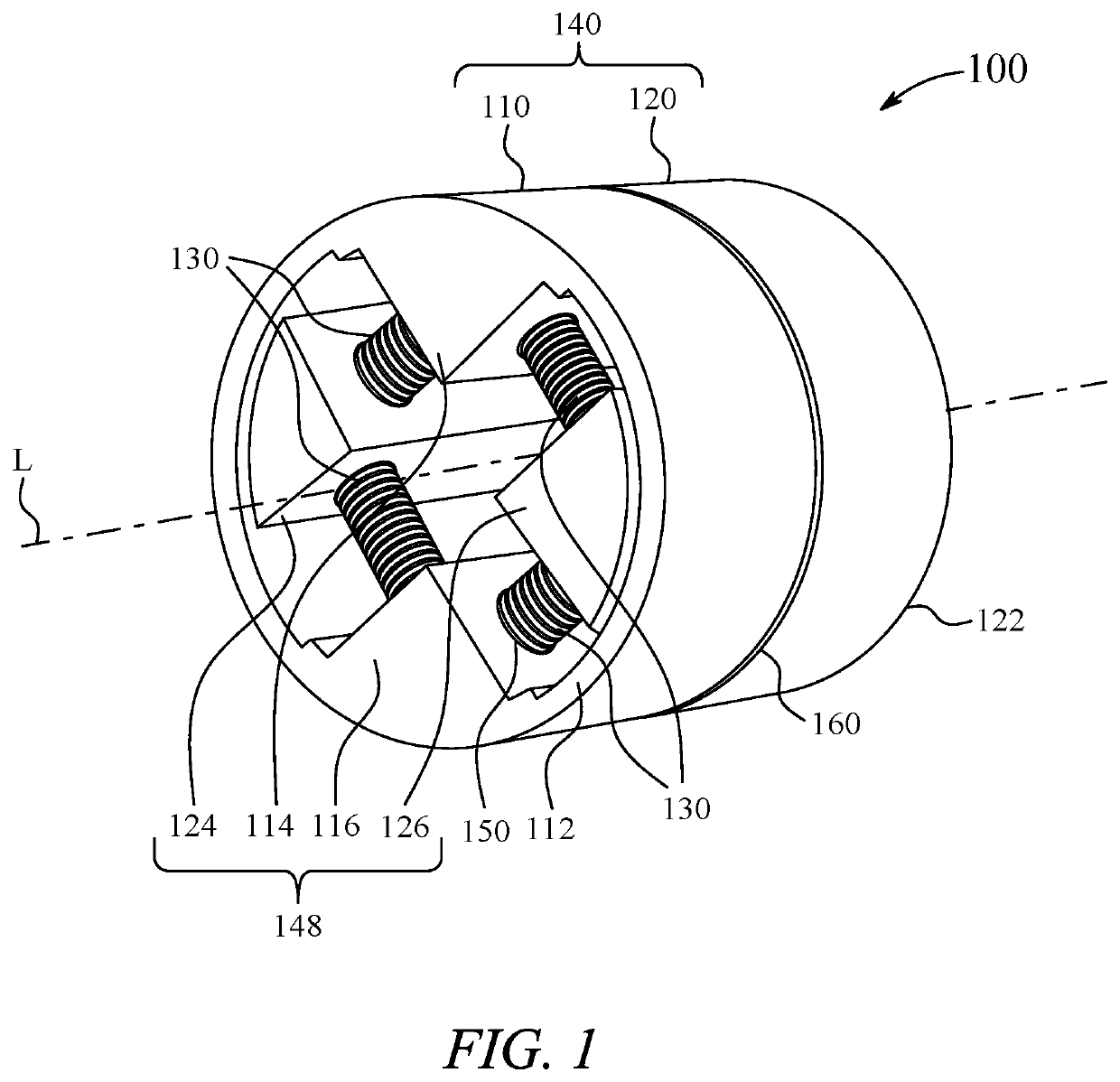
The patent describes a flexure bearing that includes a first sleeve and a second sleeve with three pillars and blind holes. The bearing also includes compression springs that connect the blind holes of adjacent pillars. The technical effect of this design is to provide a flexible bearing that can absorb and dissipate shocks and vibrations, improving the performance and reliability of the bearing.

Problems solved by technology

In some industrial applications, bearings may be used for facilitating movement between two or three elements, however, there is a restriction or limitation to use lubricants for the bearings.
In such kind of applications, flexure bearings are used to serve the same function as of the conventional bearings to facilitate movement between the elements, however, the flexure bearings provide limited angle of rotation.
Conventional flexure bearings experience fatigue failure due to cyclic loads and thus the blade design may not be a viable solution in an application that is exposed to vibration which may cause damage or lead to failure of the equipment.
Also, acceptable corrosion rate of the existing design is limited because of tight dimensional tolerance between the blades and housing of the flexure bearings.
Further, the existing designs suffer from one or more drawbacks hindering their adoption.

Method used


Image

  • Flexible bearing for compliant mechanisms
  • Flexible bearing for compliant mechanisms
  • Flexible bearing for compliant mechanisms

Examples


Embodiment Construction

[0032]In the drawings, like reference numerals designate identical or corresponding parts throughout the several views. Further, as used herein, the words “a,”“an” and the like generally carry a meaning of “one or more,” unless stated otherwise.

[0033]Furthermore, the terms “approximately,”“approximate,”“about,” and similar terms generally refer to ranges that include the identified value within a margin of 20%, 10%, or preferably 5%, and any values therebetween.

[0034]The word compliant as used in the present disclosure is defined as flexible, i.e., able to bend.

[0035]In a non-limiting example, a compliant mechanism may be a robotic joint. In another non-limiting example, a compliant mechanism may be any one of a strut joint, a tie rod joint, a steering shaft joint, and the like.

[0036]Aspects of this disclosure are directed to a single-ended flexure bearing and a double-ended flexure bearing for compliant mechanisms used in industrial applications and methods of assembling the flexur...


PUM


Abstract

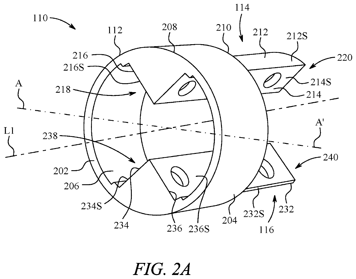
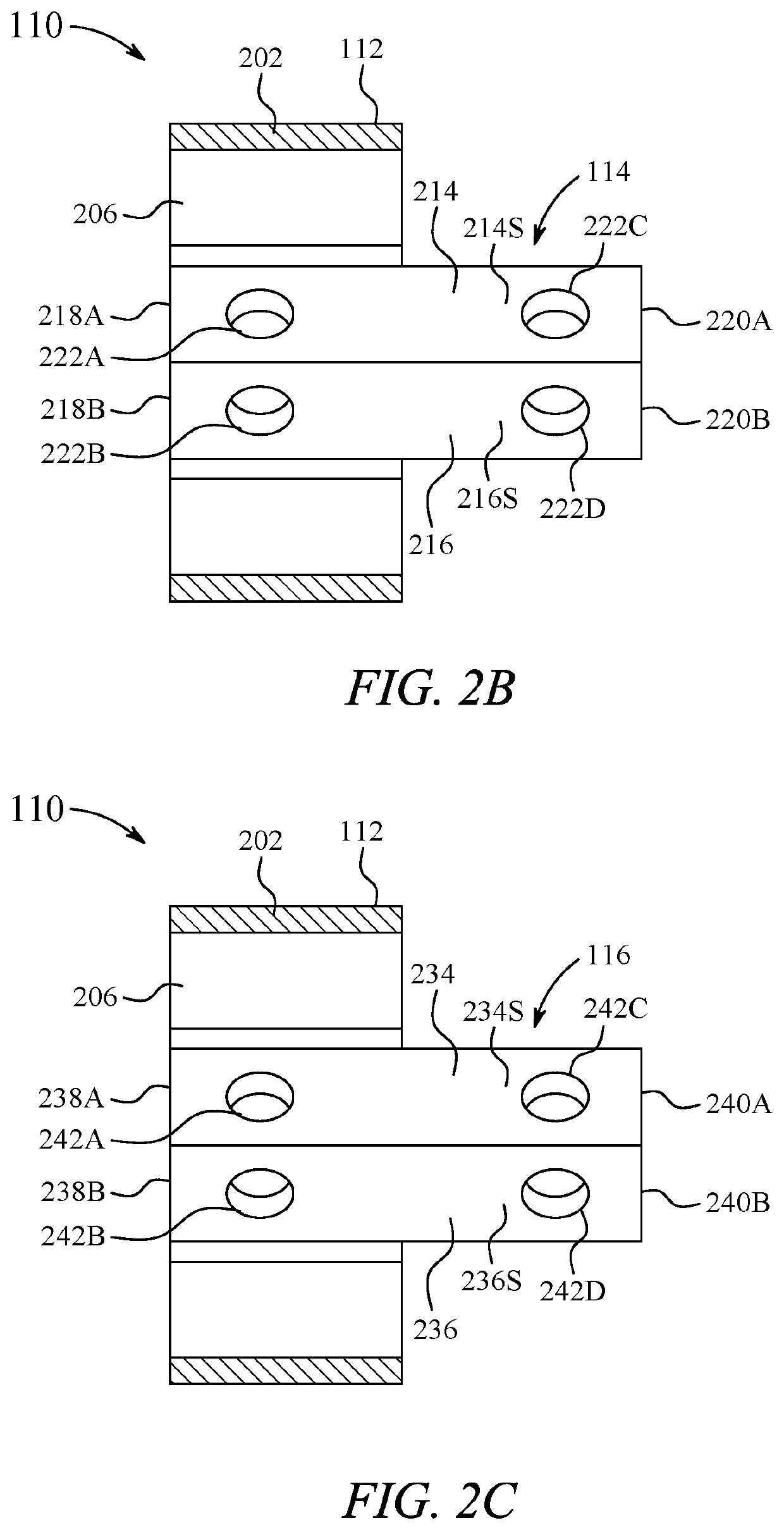
A flexure bearing having a first sleeve and a second sleeve is provided. Each sleeve includes a first pillar having a first end attached to the sleeve and a second end projecting outwardly from the sleeve and a second pillar having a first end attached to the sleeve and a second end projecting outwardly from the sleeve parallel to and diametrically opposed to the first pillar. The flexure bearing has a plurality of blind holes and a plurality of compression springs, each compression spring having a first spring end fit into one of the blind holes of a pillar of the first sleeve and a second spring end fit into a corresponding blind hole of an adjacent pillar of the second sleeve when the second sleeve is interconnected to the first sleeve.

Description

BACKGROUNDTechnical Field[0001]The present disclosure is directed to bearings used for compliant mechanisms and, more particularly, relates to flexure bearings and methods of assembling the flexure bearings.Description of Related Art[0002]The “background” description provided herein is for the purpose of generally presenting the context of the disclosure. Work of the presently named inventors, to the extent it is described in this background section, as well as aspects of the description which may not otherwise qualify as prior art at the time of filing, are neither expressly or impliedly admitted as prior art against the present invention.[0003]Bearings are generally used in various industrial applications to facilitate rotational or linear movement between two components. When such bearings are used for relative movements between two components, lubrication is applied in the bearings to ease operation thereof and to minimize wear in the moving components, which in turn increase pr...

Claims


Application Information

Patent Timeline
Patent Type & Authority Patents(United States)
IPC IPC(8): F16C11/12
CPCF16C11/12Y10T403/45Y10T403/459
Inventor ASAD, MUHAMMADKHAN, MUHAMMAD AZHAR ALIALHULAIMI, MOHAMMEDINKIS, MAJED
Owner PRINCE MOHAMMAD BIN FAHD UNIV
Learn More