Static microrelay based on bistable compliant mechanism

A flexible mechanism and micro-relay technology, applied in the direction of electrostatic relays/electro-adhesion relays, relays, circuits, etc., can solve problems such as complex structures, and achieve the effects of large working strokes, low energy consumption, and low driving voltage

Inactive Publication Date: 2010-09-15
DALIAN UNIV OF TECH
View PDF12 Cites 12 Cited by
  • Summary
  • Abstract
  • Description
  • Claims
  • Application Information

AI Technical Summary

Problems solved by technology

[0005] The principle of the electromagnetic micro-relay is basically the same as that of the traditional electromagnetic relay....

Method used


Image

  • Static microrelay based on bistable compliant mechanism
  • Static microrelay based on bistable compliant mechanism
  • Static microrelay based on bistable compliant mechanism

Examples


Embodiment 1

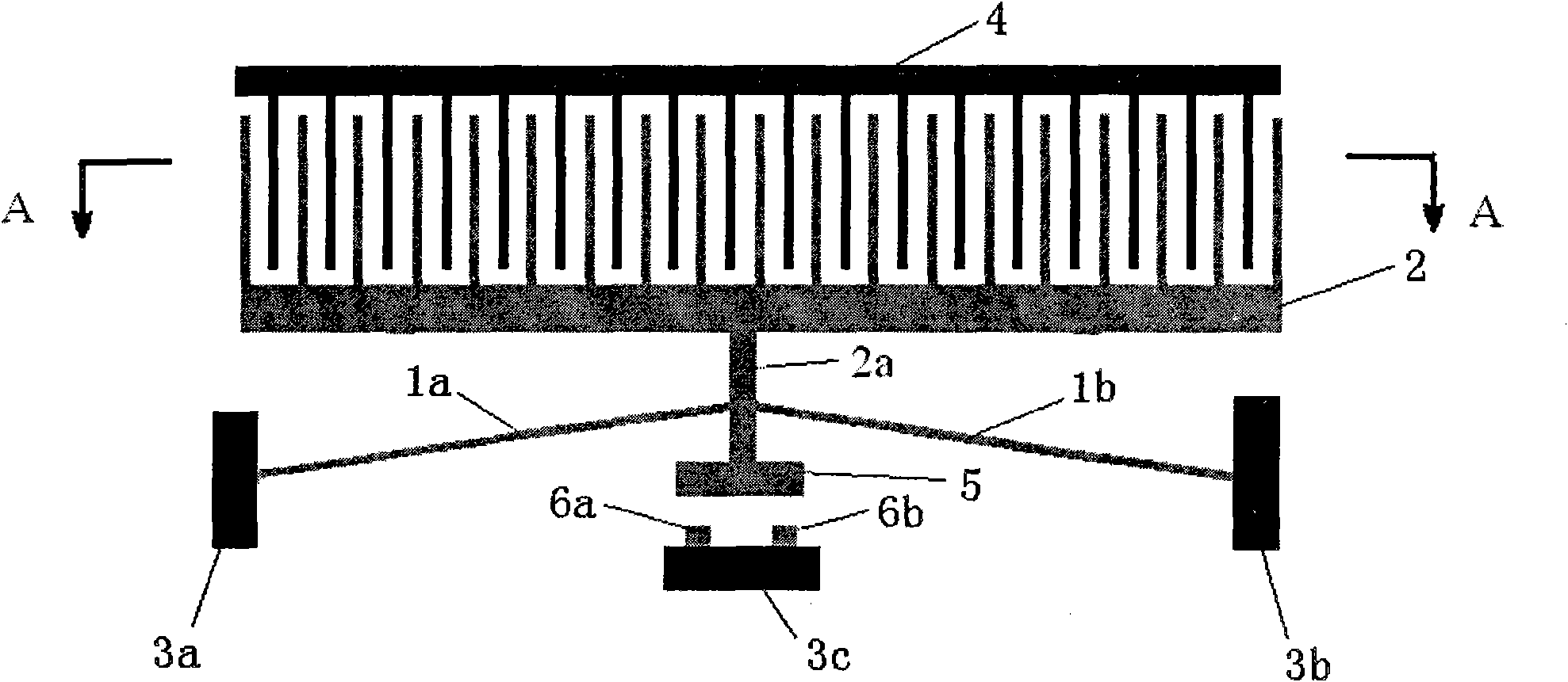
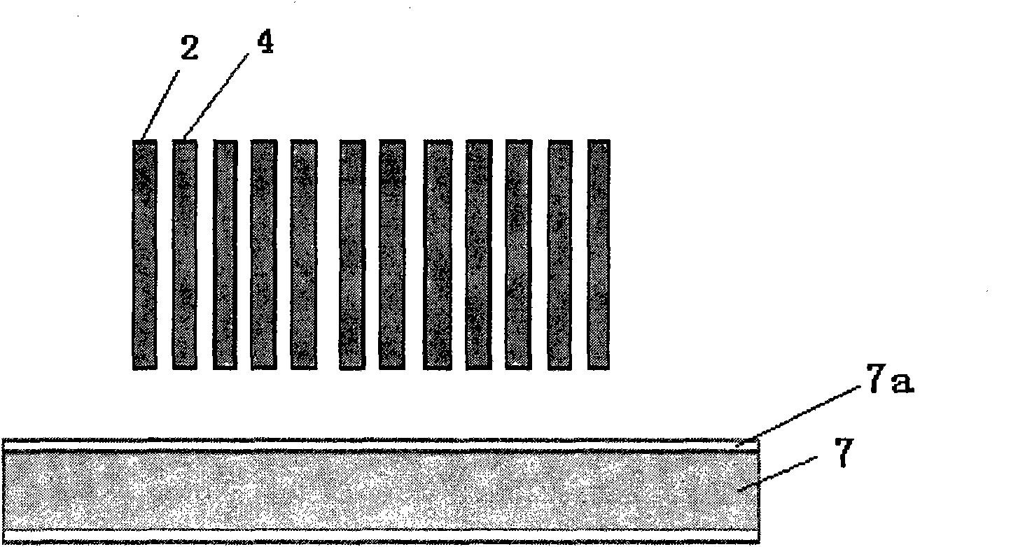
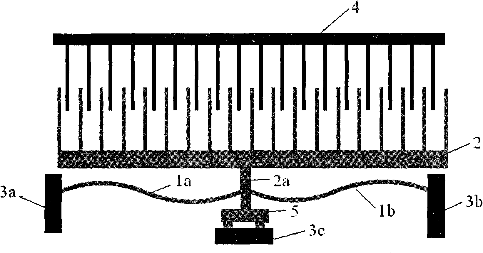
[0034] figure 1 , 2 An electrostatic microrelay based on a bistable flexible mechanism is shown. In the figure, the movable comb 2 and the movable contact 5 are connected into one body by means of a member 2a, and the bistable fully flexible beam adopts two flexible beams, one end of a left flexible beam 1a is fixed on the left insulating anchor point 3a, and the other One end is fixed on the member 2a, and one end of the other right flexible beam 1b is fixed on the right insulating anchor point 3b, and the other end is also fixed on the member 2a. The two stable positions of the bistable fully flexible beam respectively make the micro-relay in two states of closing and opening. The number of movable comb teeth 2 and fixed comb teeth 4 are equal and arranged at intervals, and the generated electrostatic force drives the action of the relay. Directly below the movable contact 5 is a left fixed contact 6a and a right fixed contact 6b fixed on the lower insulation anchor point...

Embodiment 2

[0047] Figure 13 A schematic structural diagram of an electrostatic micro-relay with two bistable flexible mechanisms is shown. On the basis of the first embodiment, two bistable micro-relays are realized with multi-point control by adopting MEMS integration technology. When the driving voltage is applied, the upper movable comb 2 drives the upper movable contact 5 to move laterally, and conducts the upper fixed contact to realize the conduction of the upper relay. At the same time, the lower movable comb 2 drives the lower movable contact 5 to generate lateral movement, and closes the lower fixed contact to realize the conduction of the lower relay. The fixed comb teeth 4 of the upper and lower relays apply the voltage in the same direction, and the action control of the upper and lower relays can be realized only by changing the input voltage direction of the upper movable comb teeth 2 and the lower movable comb teeth 2 .


PUM

PropertyMeasurementUnit
Thicknessaaaaaaaaaa
Thicknessaaaaaaaaaa
Thicknessaaaaaaaaaa

Abstract

The invention relates to a static microrelay based on a bistable compliant mechanism, belonging to static relays used in a micro-electro mechanical system (MEMS). Bistable fully-compliant beams of the static microrelay adopt two compliant beams, wherein one end of the left compliant beam is fixed on a left insulated anchor point, and the other end of the left compliant beam is fixed on a member; one end of the right compliant beam is fixed on a right insulated anchor point, and the other end of the right compliant beam is also fixed on the member; under the voltage drive, a movable comb tooth drives the bistable fully-compliant beams to transversely move and rapidly overturn to a second stable position; a movable contact is in bridging connection with a left fixed contact and a right fixed contact which are fixed on a lower insulated anchor point so as to switch a circuit on; and the relay is rapidly skipped to return to a first stable position when an aelotropic driving voltage is applied. The static microrelay substitutes a traditional linear elasticity structure by adopting the bistable compliant mechanism so as to improve the response speed and the stable holding capacity and has the characteristics of simple mechanism, short-distance drive, low energy consumption and strong anti-jamming capacity.

Description

technical field [0001] The invention relates to an electrostatic micro-relay based on a bistable flexible mechanism, which belongs to the electrostatic relay used in micro-electro-mechanical systems (MEMS), and is mainly used in communication engineering, information processing, industrial control, instrumentation and other systems. Background technique [0002] The micro-electromechanical relay based on micro-mechanical system (MEMS) technology realizes the switching of the circuit through the pull-in and disconnection of metal electrodes. It has small size, small weight, easy integration, wide bandwidth, fast response, low power consumption, and is suitable for With the advantages of mass production, it has a wide demand in communication, aerospace, automatic detection equipment and other systems. [0003] In recent years, many units and research institutions have devoted themselves to the research on the structure and driving form of micro-relays, including electrostatic ...

Claims


Application Information

Patent Timeline
IPC IPC(8): H01H59/00
Inventor 赵剑刘蓬勃常颖唐祯安胡平陈广义韩小强
Owner DALIAN UNIV OF TECH
Why Eureka
Try Eureka