Pump having a flexible mechanism for engagement with a dispenser

a flexible mechanism and pump technology, applied in the direction of liquid handling, instruments, closures using stoppers, etc., can solve the problems of frustration of the person installing the refill unit, the difficulty of inserting the refill unit into the dispenser, and the complicated engagement between the pump and the actuating mechanism of the dispenser housing

Active Publication Date: 2014-03-11
GOJO IND INC
View PDF20 Cites 12 Cited by
  • Summary
  • Abstract
  • Description
  • Claims
  • Application Information

AI Technical Summary

Benefits of technology

[0007]In light of the foregoing, it is a first aspect of the present invention to provide a refill unit for a product dispenser that is easy to install in the dispenser.
[0009]It is still another aspect of the present invention to provide a refill unit, as above, that includes a locking sleeve positioned on the connecting member to prevent unwanted actuating of the pump during shipping and installation.

Problems solved by technology

Notably, it is often difficult to insert the refill unit into the dispenser.
Often times the engagement between the pump and the actuating mechanism of the dispenser housing is complicated and requires accurate alignment of the pump and refill unit to properly be received by the dispenser housing.
This can result in difficulty and, at times, frustration on the part of the person installing the refill unit.
In addition, if inserted improperly and with too much force, the engagement mechanism or the dispenser may become broken, or the refill unit may be actuated, resulting in dispensing of foam within the dispenser.
Another problem commonly associated with foam product dispensers results when a user presses too forcefully on the actuating mechanism.
The high force applied to the actuating mechanism of the dispenser is transferred to the pump, resulting in shearing of the foam product, which causes poor quality foam to be dispensed that has a greater than desired liquid content.

Method used


Image

  • Pump having a flexible mechanism for engagement with a dispenser
  • Pump having a flexible mechanism for engagement with a dispenser
  • Pump having a flexible mechanism for engagement with a dispenser

Examples


Embodiment Construction

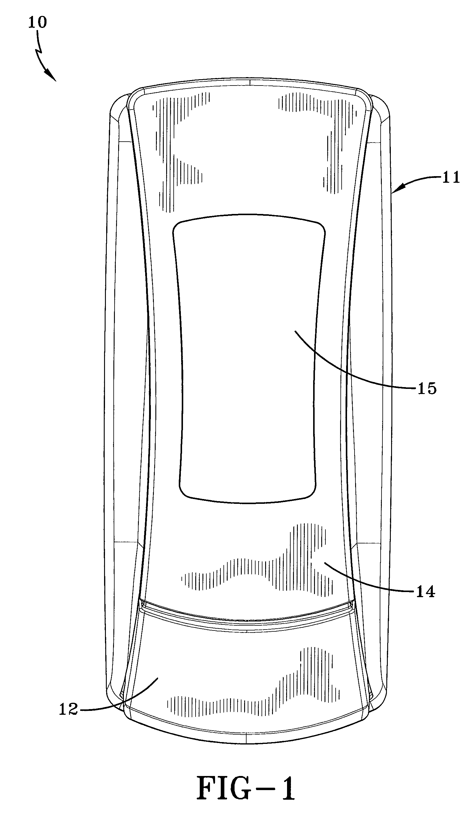
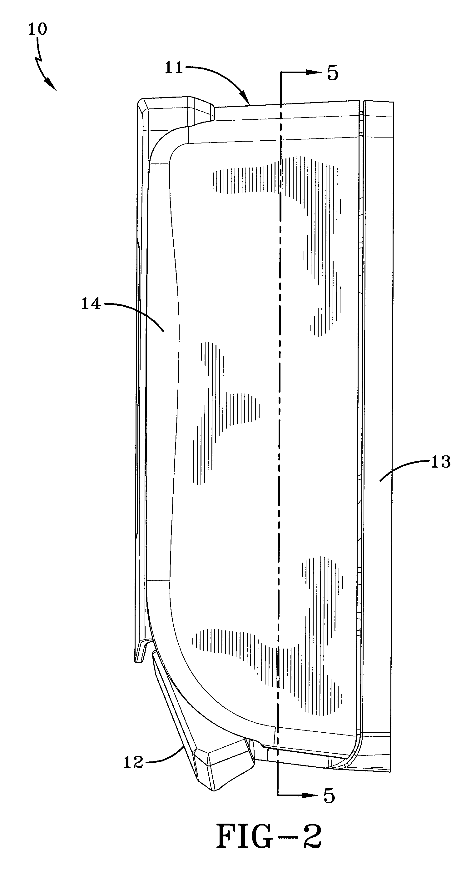
[0035]Referring now to FIGS. 1 and 2, a conventional product dispenser is shown and is generally indicated by the numeral 10. Dispenser 10 includes a housing 11 including a push bar 12, a back plate 13 (FIG. 2) and a pivoting cover 14. As is well known in the art, cover 14 pivots on back plate 13 to provide access to an internal cavity for refilling the dispenser. While a particular housing configuration for providing access to the internal cavity is contemplated and described herein, it should be appreciated that any such mechanism known to those skilled in the art may be employed. Push bar 12 is pressed by a user to actuate the foam pump within dispenser 10, and is biased to return to its non-actuated state after use. A window 15 may optionally be provided in cover 14 to allow visual inspection of the fluid level within the liquid reservoir in the dispenser 10.

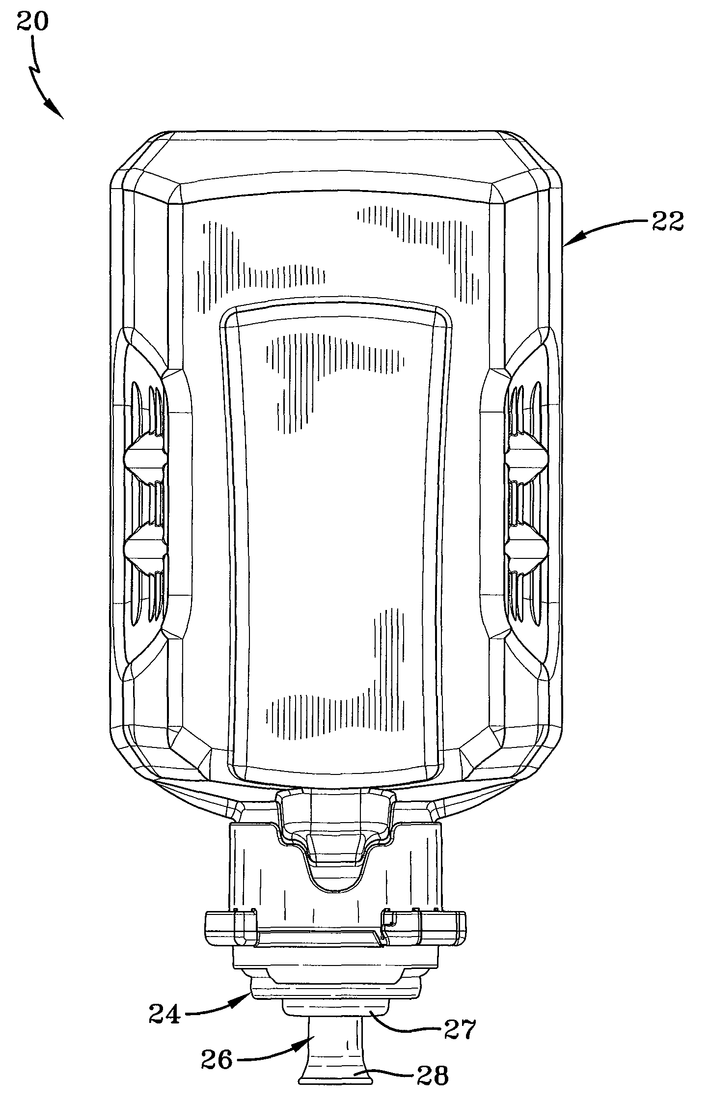
[0036]FIGS. 3-4A depict a refill unit 20 that is to be inserted into housing 11 of dispenser 10. Refill unit 20 includes a...


PUM

PropertyMeasurementUnit
flexibleaaaaaaaaaa
conical shapeaaaaaaaaaa
hardnessaaaaaaaaaa

Abstract

A foam pump having a flexible member for engagement with a dispenser, the pump being part of a refill unit including a product reservoir. The flexible connecting member extends from an extreme end of the pump and is received by an actuating carriage that is movably connected to an actuating mechanism. The flexible connecting member permits insertion of the pump into a dispenser, and may act to dampen actuating forces to reduce foam shearing. The flexible connecting member may be provided in the form of a flared tip that is received through an oval opening in the product dispenser, and the pump may include a locking member to prevent unwanted actuation thereof during insertion of the refill unit into the dispenser.

Description

[0001]This application claims priority from U.S. provisional patent application Ser. No. 61 / 191,739 filed on Sep. 11, 2008, which is incorporated herein by reference in its entirety.FIELD OF THE INVENTION[0002]The invention herein relates to a foam pump having a flexible mechanism for engagement with a foam product dispenser. More particularly, the invention relates to a flexible mechanism carried by a foam pump that allows the pump to be positioned within a dispenser and is received by an actuating carriage of the dispenser.BACKGROUND OF THE INVENTION[0003]It is well known in the art of foam pumps to provide a refill unit that is inserted into a foam product dispenser housing. The refill unit includes a product reservoir and a pump and is placed in the dispenser housing to create a product dispenser. Part of the dispenser housing, often the cover, pivots to expose an internal cavity defined by the housing and to allow the refill unit to be removed, when the product reservoir is emp...

Claims


Application Information

Patent Timeline
Patent Type & Authority Patents(United States)
IPC IPC(8): B65D88/54B67D7/06
CPCB05B11/3057B05B11/3014B05B11/0059B05B11/3059B05B11/3087A47K5/1207B05B11/0054Y10T29/49826B05B11/1014B05B11/1059B05B11/1057B05B11/1087B65D83/00B05B11/00A47K5/14A47K5/12
Inventor CIAVARELLA, NICK E.HAYES, DAVID D.CROWE, JOSEPH E.QUINLAN, JR., ROBERT L.
Owner GOJO IND INC
Why Eureka
Try Eureka