
Electrical contact

a technology of electrical contact and contact plate, which is applied in the direction of coupling contact member, coupling device connection, electrical apparatus, etc., can solve the problems of reducing the size of the connector design, and achieve the effect of minimizing the contact dimension and more resiliency

Active Publication Date: 2022-05-31
FOXCONN (KUNSHAN) COMPUTER CONNECTOR CO LTD +1
View PDF16 Cites 0 Cited by
  • Summary
  • Abstract
  • Description
  • Claims
  • Application Information

AI Technical Summary

Benefits of technology

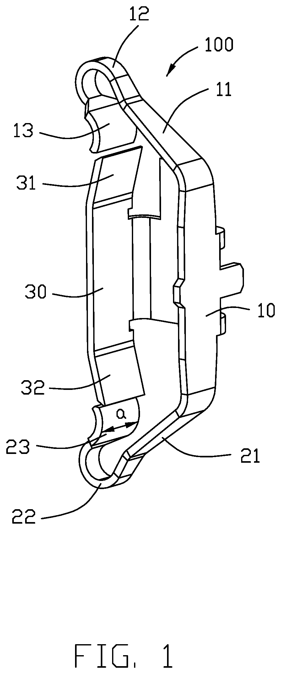
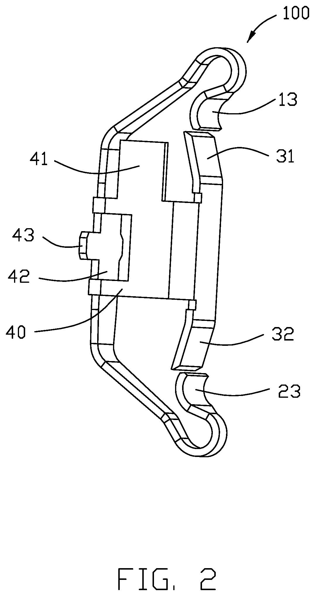
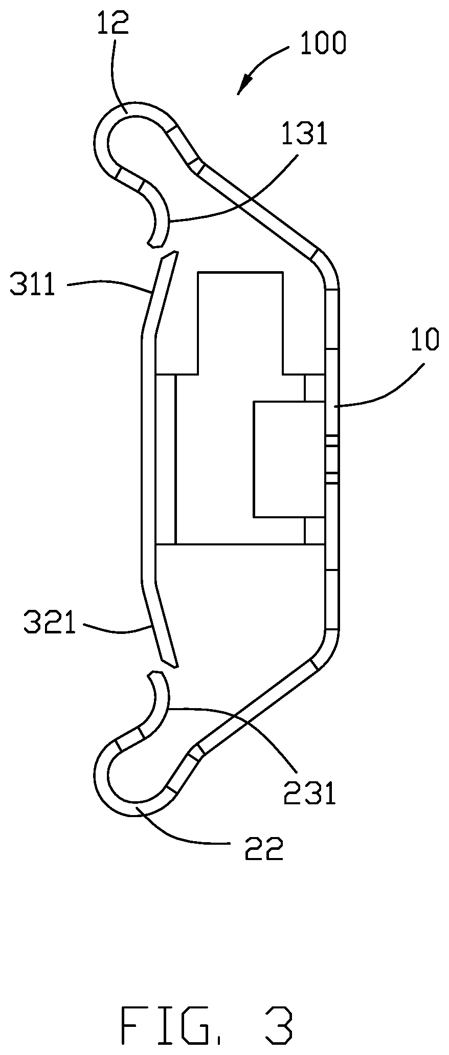
[0004]To achieve the above object, an electrical contact for connecting a CPU (Central Processing Unit) and a PCB (Printed Circuit Board), includes a retention section of an outer part and an extension section of an inner part parallel to each other and linked to each other via a transverse bridge located in another vertical plane perpendicular to both the retention section and the extension section. An upper contacting arm extends, toward the extension section, from an upper end of the retention section with an upper mating apex and an upper abutment tip region, and a lower contacting arm extends, toward the extension, from a lower end of the retention section with a lower mating apex and a lower abutment tip region. An upper abutment tab upwardly and obliquely extends from an upper end of the extension section toward the retention section and adapted to be coupled with the upper abutment tip region when the upper contacting arm is downwardly depressed by the CPU, and a lower abutment tab downwardly and obliquely extends from the lower end of the extension section toward the retention section and adapted to be coupled with the lower abutment tip region when the lower contacting arm is upwardly depressed by the PCB. Because the abutment tab of the inner part extends toward the outer part, thus minimizing the dimension of the contact along the extending direction of the contacting arm. Because the bridge may provide the inner part with more resiliency, the coupling between the abutment tip region of the outer part and the abutment tab of the inner part may be properly implemented.

Problems solved by technology

On one hand, because the inner contacting arm extends along the same direction with the outer contacting arm, it takes more space, thus hindering miniaturization of the connector design; on the other hand, because the middle vertical plane is essentially immovable, the inner contacting arm may be relatively rigid when shortening the inner contacting arm for miniaturization, thus being unwelcome for coupling between the outer contacting arm and the inner contacting arm.

Method used


Image

  • Electrical contact
  • Electrical contact
  • Electrical contact

Examples


Embodiment Construction

[0012]Referring to FIGS. 1-3, an electrical contact 100 includes an outer part and inner part linked by a bridge. The outer part includes a retention section 10 and the inner part includes an extension section 30 linked transversely with the retention section 10 via the bridge or connection section 40. A resilient upper contacting arm 11 extends from an upper end of the retention section 10 toward the extension section 30 with an upper mating apex 12 and an upper abutment tip region 13 which downwardly extends from the upper mating apex 12 toward the extension section 30. Symmetrically, a resilient lower contacting arm 21 extends from a lower end of retention section 10 toward the extension section 30 with a lower mating apex 22 and a lower abutment 23 tip region which upwardly extends from the lower mating apex 22 toward the extension section 30. Correspondingly, an upper abutment tab 31 extends upwardly and obliquely from the upper end of the extension section 30 toward the retent...


PUM


Abstract

An electrical contact includes a retention section of an outer part and an extension section of an inner part parallel to each other and linked to each other via a transverse bridge located in another vertical plane perpendicular to both the retention section and the extension section. An upper contacting arm extends, toward the extension section, from an upper end of the retention section with an upper mating apex and an upper abutment tip region, and a lower contacting arm extends, toward the extension, from a lower end of the retention section with a lower mating apex and a lower abutment tip region. An upper abutment tab upwardly and obliquely extends from an upper end of the extension section toward the retention section and adapted to be mated with the upper abutment tip region when the upper contacting arm is downwardly depressed by the CPU.

Description

BACKGROUND OF THE INVENTION1. Field of the Invention[0001]The present invention relates to an electrical contact for use within an electrical connector, and particularly to the contact having multiple transmission paths.2. Description of Related Arts[0002]U.S. Pat. No. 9,882,296 discloses the contact having the retaining section located in a middle vertical plane, a pair of outer contacting arms extending from an outer vertical plane, and a pair of inner contacting arms extending from an inner vertical plane, wherein the outer vertical plane and the inner vertical plane are parallel to each other and both are perpendicular to the middle vertical plane, and the outer contacting arms are deflected to contact the corresponding inner contacting arms, respectively, during operation. On one hand, because the inner contacting arm extends along the same direction with the outer contacting arm, it takes more space, thus hindering miniaturization of the connector design; on the other hand, be...

Claims


Application Information

Patent Timeline
Patent Type & Authority Patents(United States)
IPC IPC(8): H01R13/24H01R12/71H01R12/70
CPCH01R13/2407H01R12/7082H01R12/712H01R13/2435H01R13/2464H01R12/7076H01R12/714
Inventor HSU, SHUO-HSIU
Owner FOXCONN (KUNSHAN) COMPUTER CONNECTOR CO LTD
Learn More