Supercharge Your Innovation With Domain-Expert AI Agents!

Component mounting machine and method for determining dropping of component

a technology of component mounting machine and component, which is applied in the direction of metal working equipment, metal-working equipment, manufacturing tools, etc., can solve the problems of component dropping erroneously, and achieve the effect of curtailing the cost requirement for the determination of the dropped componen

Active Publication Date: 2022-05-31
FUJI CORP
View PDF12 Cites 0 Cited by
  • Summary
  • Abstract
  • Description
  • Claims
  • Application Information

AI Technical Summary

Benefits of technology

Enables indirect and logical determination of component dropages without additional sensors, maintaining production efficiency by allowing continuous operation and reducing costs associated with new detection systems.

Problems solved by technology

When picking up components using a suction nozzle, there are rare cases in which a component is erroneously dropped.

Method used


Image

  • Component mounting machine and method for determining dropping of component
  • Component mounting machine and method for determining dropping of component
  • Component mounting machine and method for determining dropping of component

Examples


Embodiment Construction

1. Configuration of Component Mounting Machine 1 of a First Embodiment

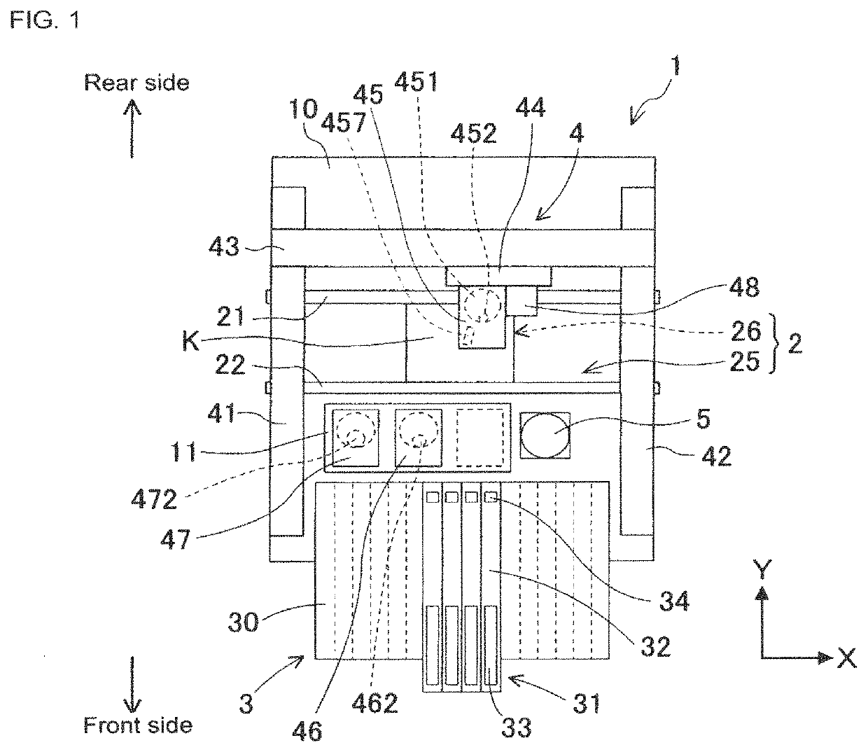
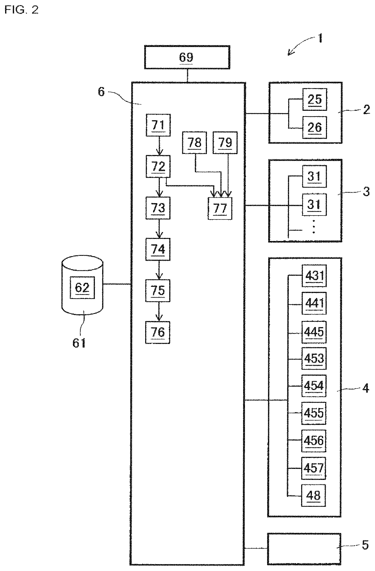
[0018]Component mounting machine 1 of an embodiment will be described with reference to FIGS. 1 to 8. FIG. 1 is a plan view schematically showing the configuration of component mounting machine 1 of an embodiment. The direction from the left side to the right side in FIG. 1 is the X-axis direction in which board K is conveyed, and a direction from the lower side to the upper side in FIG. 1 is the Y-axis direction (front-rear direction). FIG. 2 is a block diagram showing the configuration of control items of component mounting machine 1 of the embodiment. Component mounting machine 1 is configured from board conveyance device 2, component supply device 3, component transfer device 4, component camera 5, control device 6, and the like, assembled on base 10. Board conveyance device 2, component supply device 3, component transfer device 4, and component camera 5 are controlled from control device 6 such that each per...


PUM


Abstract

A component mounting machine including a component supply device to supply a component to a supply position; a component transfer device to use a component mounting tool to pick up the component from the supply position and mount the component on a board; a component detecting section to detect whether the component is present at the supply position before or while the component is being picked up by the component mounting tool; a holding detecting section to detect whether the component mounting tool is holding the component following pickup; and a remaining detecting section to detect whether the component remains at the supply position in a case in which it is detected by the holding detecting section that the component is not being held by the component mounting tool; and a dropped determining section to determine whether the component has dropped.

Description

TECHNICAL FIELD[0001]The present specification relates to a component mounting machine for performing a mounting operation for mounting electronic components (also referred to as components) on a board.BACKGROUND ART[0002]Technology for mass production of circuit boards by performing various operations (hereinafter referred to as board operations) for mounting components on a board on which printed wiring has been applied has become widespread. A solder printer, component mounter, reflow oven, board inspecting machine or the like is used as a board work machine for performing work with respect to a board. Component mounters generally include: a board conveyance device; component supply devices; and a component transfer device. A component transfer device includes: a mounting head for holding a suction nozzle; a head drive mechanism for horizontally driving the mounting head in two directions; and the like. When picking up components using a suction nozzle, there are rare cases in wh...

Claims


Application Information

Patent Timeline
Patent Type & Authority Patents(United States)
IPC IPC(8): B23P19/00H05K13/04H05K13/08H05K13/02
CPCH05K13/0452H05K13/02H05K13/0409H05K13/0413H05K13/0812H05K13/0417H05K13/082
Inventor KITO, RIEKAWAI, HIDETOSHIHOSOI, NORIONOZAWA, MIZUHOIISAKA, JUNITO, HIDETOSHIFUJIMURA, SHINGOISHIKAWA, KENZOYAMAKAGE, YUSUKE
Owner FUJI CORP
Features
  • R&D
  • Intellectual Property
  • Life Sciences
  • Materials
  • Tech Scout
  • Unparalleled Data Quality
  • Higher Quality Content
  • 60% Fewer Hallucinations
Learn More