
Rotary pump with rotor bearing ring

a technology of rotor bearings and rotors, which is applied in the direction of pump components, machines/engines, liquid fuel engines, etc., can solve the problems of not specifically addressing sealing, and achieve the effect of improving sealing characteristics

Active Publication Date: 2022-06-07
THE BRICKS GRP
View PDF3 Cites 0 Cited by
  • Summary
  • Abstract
  • Description
  • Claims
  • Application Information

AI Technical Summary

Benefits of technology

Enables quick and efficient disassembly and reassembly of the pump without tools, enhancing maintenance efficiency and providing improved sealing characteristics for rotor and shaft movement.

Problems solved by technology

While these three designs have rotor pads on the faces that face the cover (and opposing side) in an effort to reduce wear on the rotors themselves, they do not specifically address sealing.

Method used


Image

  • Rotary pump with rotor bearing ring
  • Rotary pump with rotor bearing ring
  • Rotary pump with rotor bearing ring

Examples


Embodiment Construction

[0030]Example embodiments will now be described more fully with reference to the accompanying drawings.

[0031]Example embodiments are provided so that this disclosure will be thorough, and will fully convey the scope to those who are skilled in the art. Numerous specific details are set forth such as examples of specific components, devices, and methods, to provide a thorough understanding of embodiments of the present disclosure. It will be apparent to those skilled in the art that specific details need not be employed, that example embodiments may be embodied in many different forms and that neither should be construed to limit the scope of the disclosure. In some example embodiments, well-known processes, well-known device structures, and well-known technologies are not described in detail.

[0032]The terminology used herein is for the purpose of describing particular example embodiments only and is not intended to be limiting. As used herein, the singular forms “a,”“an,” and “the” ...


PUM


Abstract

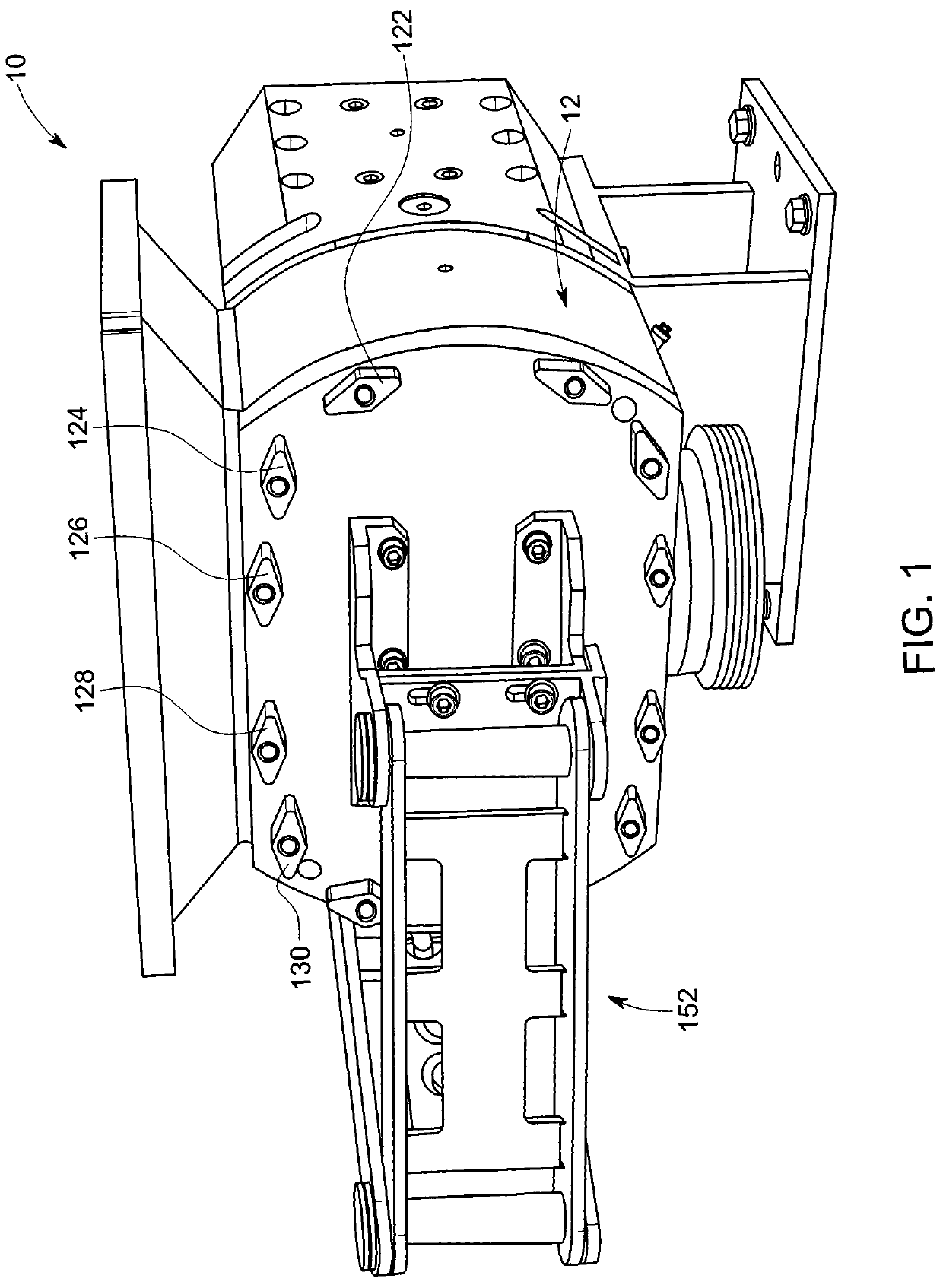
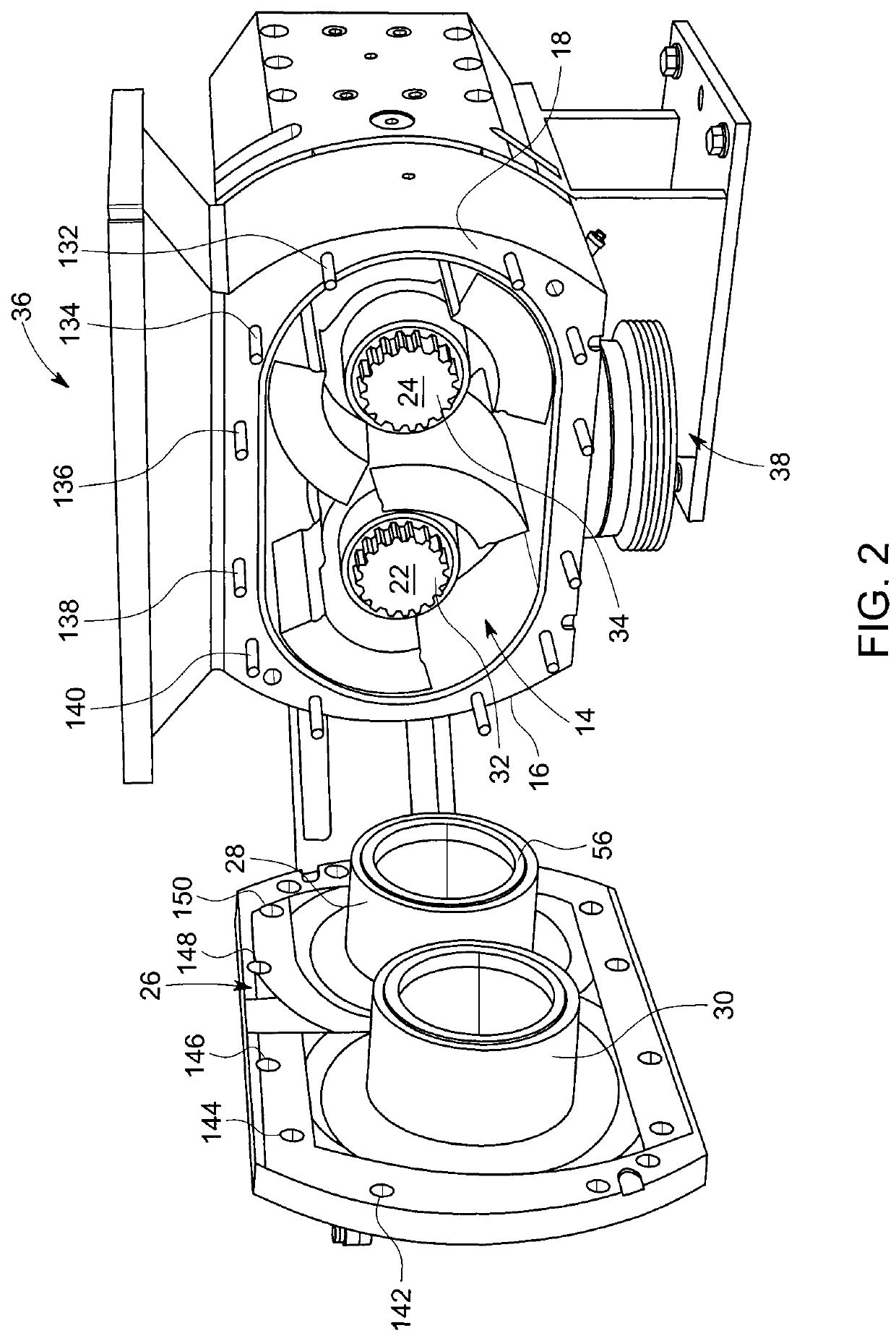
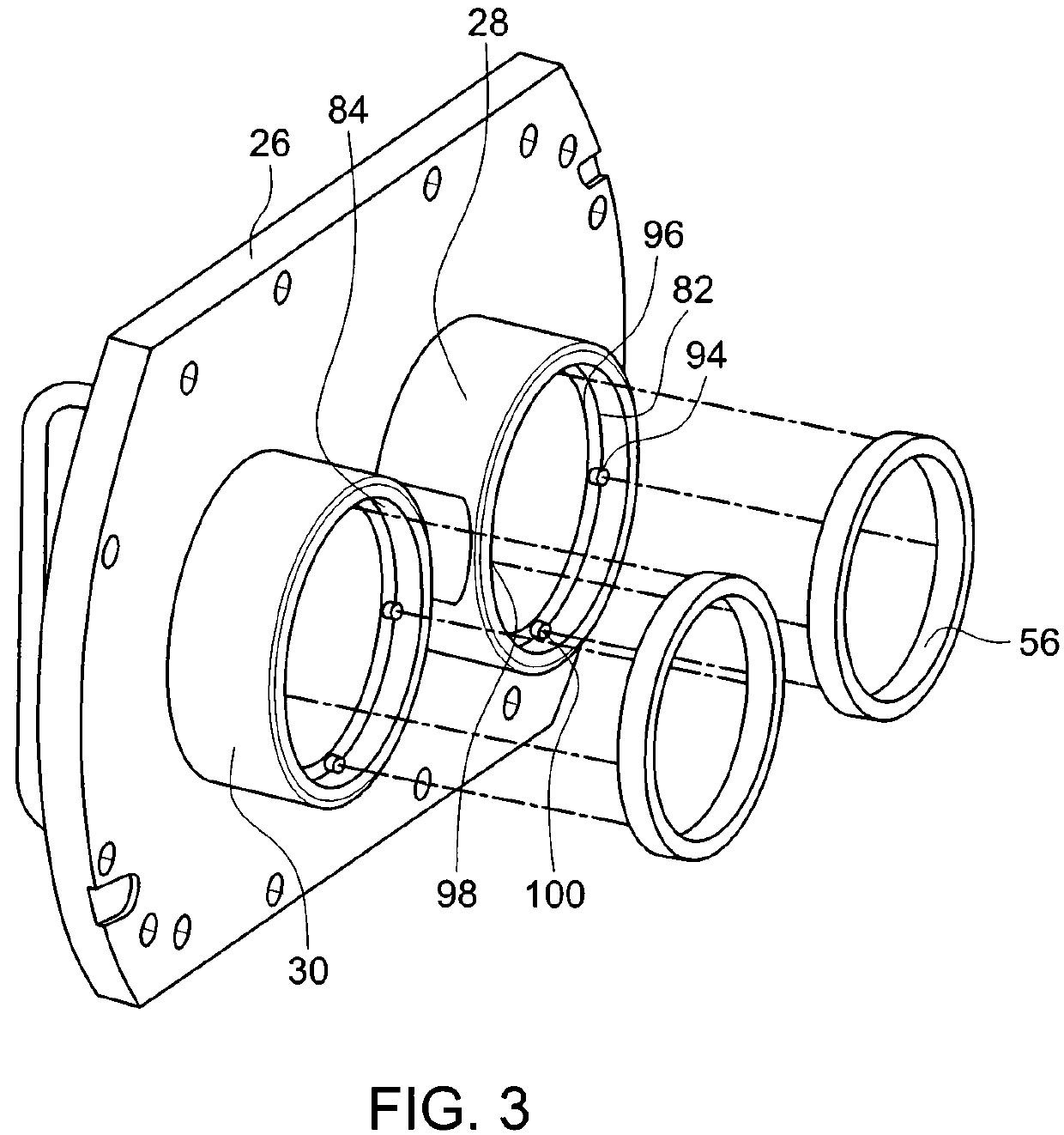
Lobe pumps have rings which can be located at least partially in at least one of cover plates and rotors, if not both to provide at least thrust bearings to space the rotors from the cover plates. Some rotors may have voids in ears to make the rotor lighter in weight with the voids potentially capped, symmetrically disposed, arcuately shaped and / or have other desirable features. Some rotors may have ears extending beyond cutouts which may extend beyond hubs, if not beyond hub extensions as well which may receive cover spigots thereabout. Some rings may act as radial bearings as well when located in the cover spigots.

Description

FIELD OF THE INVENTION[0001]The present invention relates to a rotary pump construction such as a positive displacement pump and more particularly to such pumps potentially having improved rotor constructions with at least one of easy to clean feature, voids in the rotor, improved rotor sealing characteristics and / or improved rotor bearing performance over prior art pumps.BACKGROUND OF THE INVENTION[0002]The applicant is the owner of at least U.S. Pat. Nos. 8,087,914, 9,017,052, and 9,377,021 for improved positive displacement pumps with rotors. These designs have been well received in the marketplace.[0003]While these three designs have rotor pads on the faces that face the cover (and opposing side) in an effort to reduce wear on the rotors themselves, they do not specifically address sealing. Furthermore, the covers on these designs are typically secured with nuts such as nut 20 in U.S. Pat. No. 9,937,021 requiring a wrench for installation / removal.[0004]In the field of food servi...

Claims


Application Information

Patent Timeline
Patent Type & Authority Patents(United States)
IPC IPC(8): F04C2/26F04C15/00F04C2/08F04C2/12
CPCF04C2/086F04C2/126F04C15/0026F04C2240/20F04C2240/30F04C2240/50F04C2240/805F04C2250/20F04C2/084F04C15/0073
Inventor DANIELSSON, CARL MAGNUS
Owner THE BRICKS GRP
Learn More