
Wearable chair with truss structure

a technology of trusses and wearable chairs, which is applied in the direction of wheelchairs/patient conveyances, convertible stools, chairs, etc., can solve the problems of low stability of active wearable robots, limited seating angles, and difficulty in changing the seating angle of chairs, so as to minimize the interference of wearers walking and improve seating stability

Active Publication Date: 2022-06-14
HYUNDAI MOTOR CO LTD +1
View PDF33 Cites 0 Cited by
  • Summary
  • Abstract
  • Description
  • Claims
  • Application Information

AI Technical Summary

Benefits of technology

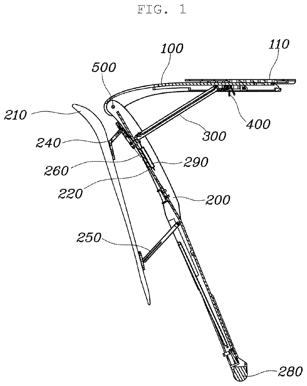
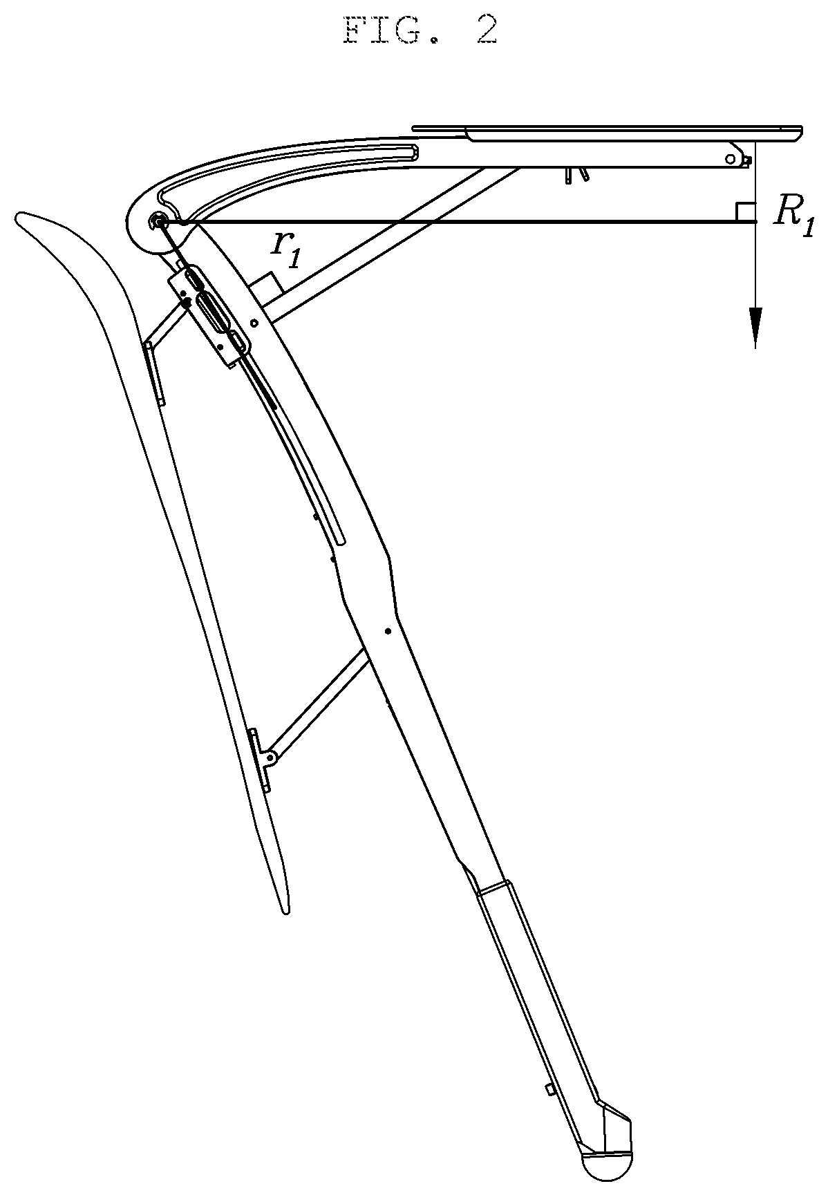
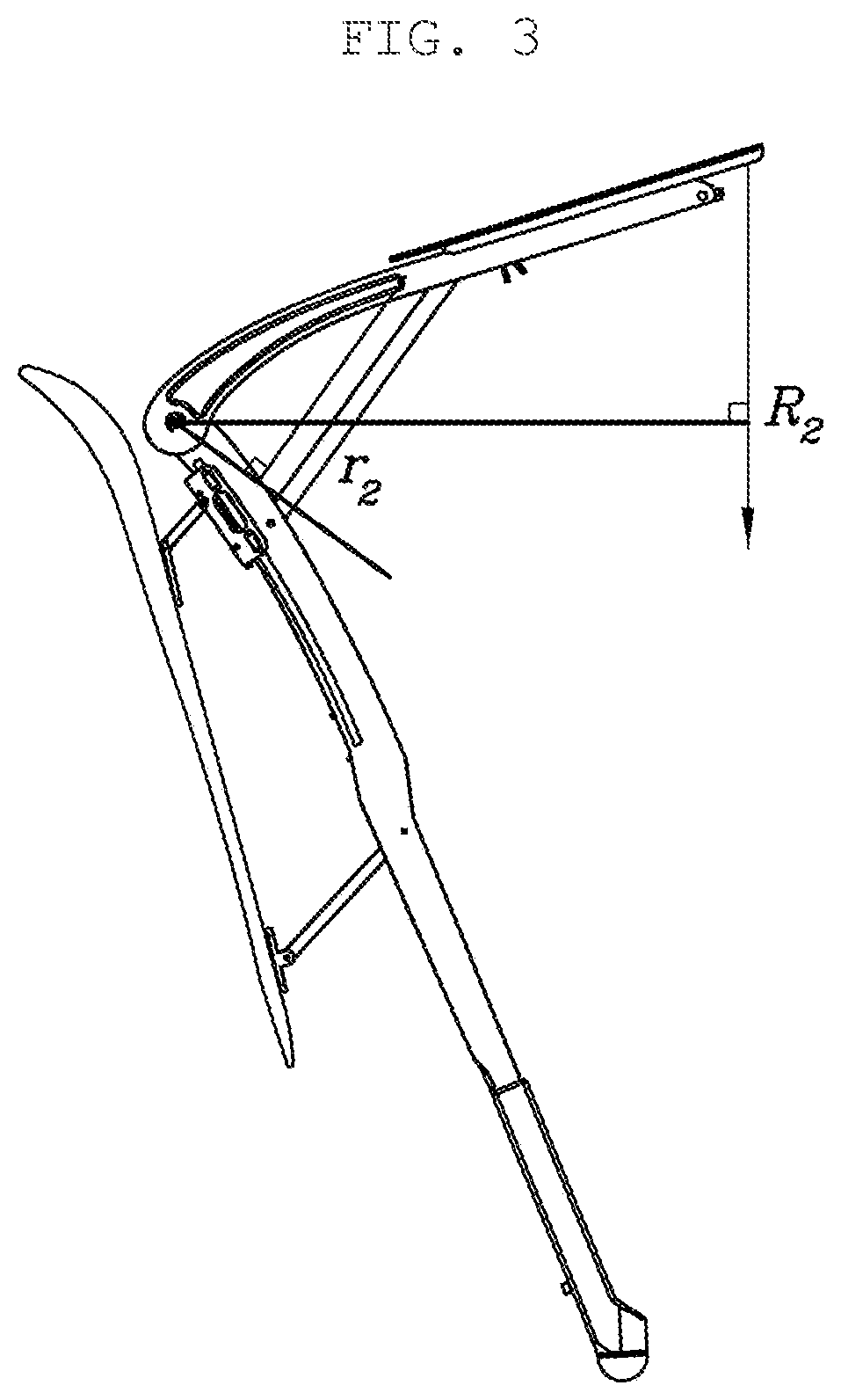
[0023]The wearable chair with a truss structure of the present invention can support a heavy weight with a lightweight structure of the chair despite having a changeable seating angle.
[0024]In addition, in a case in which when the wearer sits, the lower rod is lowered relative to the lower leg fixing part and the lower end part of the lower rod is in contact with the ground, the lower end part of the lower rod is located to be spaced apart from the wearer's foot due to a four-link structure of the lower rod and the lower leg fixing part, thereby improving seating stability.
[0025]In addition, in a wearer's standing posture, the lower end part of the lower rod is maintained to be raised from the ground such that the lower end part of the lower rod is not in contact with the ground, thereby minimizing the interference of the wearer's walking.

Problems solved by technology

However, an active type wearable robot that assists muscle strength by acting on power has a relatively heavy weight and requires complex control by a controller, so the active type wearable robot has low stability and a limited seating angle.
However, in the passive type wearable chair according to the conventional technology, it is difficult to change the seating angle of the chair.

Method used


Image

  • Wearable chair with truss structure
  • Wearable chair with truss structure
  • Wearable chair with truss structure

Examples


Embodiment Construction

[0031]Specific structural and functional descriptions of the embodiment of the present invention disclosed herein are only for illustrative purposes of the embodiment of the present invention. The present invention may be embodied in many different forms without departing from the spirit and significant characteristics of the present invention. Therefore, the embodiment of the present invention is disclosed only for illustrative purposes and should not be construed as limiting the present invention.

[0032]Reference will now be made in detail to the embodiment of the present invention, a specific example of which is illustrated in the accompanying drawings and described below, since the embodiment of the present invention can be variously modified in many different forms. While the present invention will be described in conjunction with the exemplary embodiment thereof, it is to be understood that the present description is not intended to limit the present invention to the exemplary ...


PUM


Abstract

Proposed is a wearable chair with a truss structure, the wearable chair including: an upper rod extending in a longitudinal direction thereof and connected to a wearer's thigh; a lower rod extending in a longitudinal direction thereof and connected to a lower leg of the wearer, the lower rod being coupled to a lower end part of the upper rod at an upper end part of the lower rod and being in contact with the ground at a lower end part of the lower rod when the wearer sits; and a support rod slidably coupled to the upper rod at an upper end part of the support rod and rotatably coupled to the lower rod at a lower end part of the support rod to support a compression force between the upper rod and the lower rod in a longitudinal direction of the support rod when the wearer sits.

Description

TECHNICAL FIELD[0001]The present invention relates generally to a wearable chair with a truss structure. More particularly, the present invention relates to a chair which supports a wearer's weight when the wearer sits while wearing the chair.BACKGROUND ART[0002]Currently, wearable robots used for a variety of purposes, such as assisting the movement of the disabled and the elderly by supporting their muscle strength, for rehabilitation treatment for patients with muscle disease, for military personnel carrying heavy military gear, or for industrial sites in which heavy loads are carried are actively being developed.[0003]Generally, a wearable robot is manufactured by organically combining links performing joint action similar to the joint action of the human body such that the links have a shape capable of being worn on the human body. Such a wearable robot is worn by a user to assist the upper or lower limb muscle strength of the user so that the user can perform a high-load opera...

Claims


Application Information

Patent Timeline
Patent Type & Authority Patents(United States)
IPC IPC(8): A61G5/14A47C9/10A47C13/00
CPCA47C13/00A47C9/025F16B2200/83A47C9/00A47C7/002A47C7/62
Inventor BAE, KI HYEONJUNG, KYUNG MOKIM, KYU JUNGYOON, JU YOUNGHYUN, DONG JIN
Owner HYUNDAI MOTOR CO LTD
Learn More