
Motor

a motor and motor core technology, applied in the field of motors, can solve the problems of leakage to the outside of the rotor core, downward flow of applied adhesive,

Active Publication Date: 2022-06-14
LG INNOTEK CO LTD
View PDF10 Cites 0 Cited by
  • Summary
  • Abstract
  • Description
  • Claims
  • Application Information

AI Technical Summary

Benefits of technology

[0024]According to embodiments, an advantageous effect is provided in that an adhesive is inhibited from flowing downward and leaking to the outside of a rotor core.
[0025]An advantageous effect is provided in that performance of the motor is secured.
[0026]An advantageous effect is provided in that, even when a magnet is positioned right below a sensing plate, an upper end portion of the magnet is sufficiently magnetized when a sensing magnet and the magnet are simultaneously magnetized.

Problems solved by technology

The adhesive may be applied into the pocket, and there is a problem in that the applied adhesive flows downward and leaks to the outside of the rotor core.

Method used


Image

  • Motor
  • Motor
  • Motor

Examples


Embodiment Construction

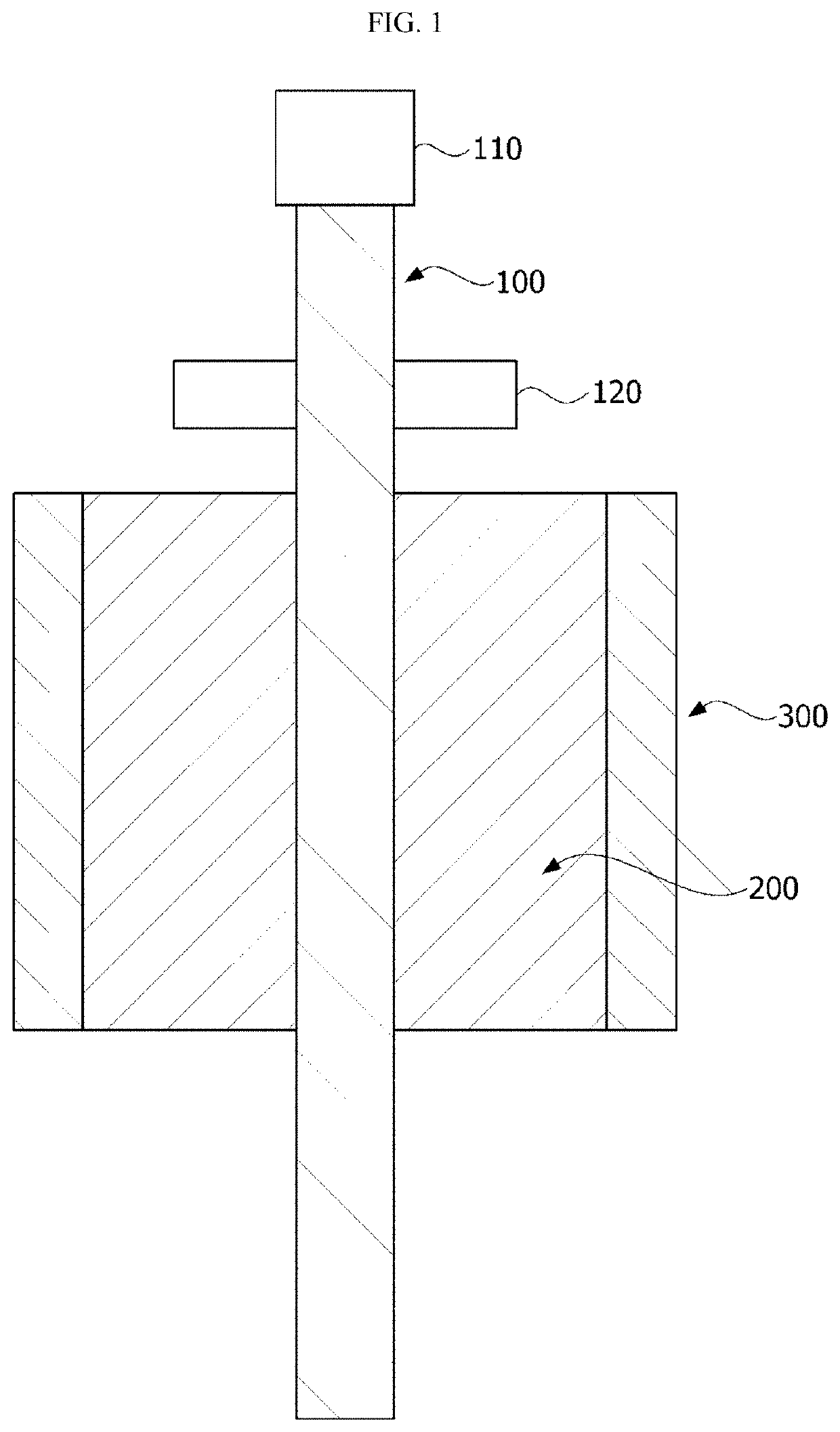
[0042]Hereinafter, exemplary embodiments of the present invention will be described in detail with reference to the accompanying drawings. Purposes, specific advantages, and novel features of the invention will be made clear from the exemplary embodiments and the following detailed description in connection with the accompanying drawings. In the description of the invention, detailed descriptions of related well-known functions which unnecessarily obscure the gist of the invention thereof will be omitted.

[0043]Although the terms “first,”“second,” etc. may be used herein to describe various elements, these elements should not be limited by these terms. These terms are only used to distinguish one element from another. For example, a first element could be termed a second element, and a second element could similarly be termed a first element without departing from the scope of the present invention. As used herein, the term “and / or” includes combinations or any one of a plurality of ...


PUM


Abstract

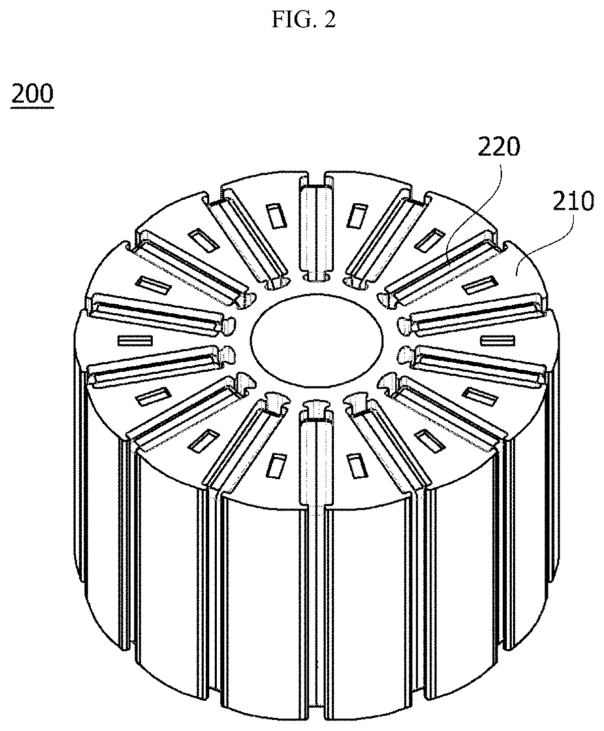
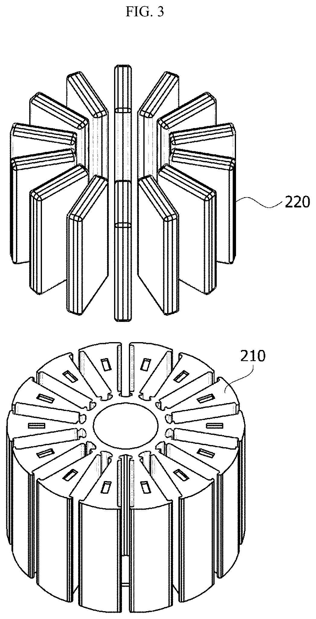
The present invention may provide a motor including a shaft, a rotor disposed outside the shaft, and a stator disposed outside the rotor, wherein the rotor includes a rotor core surrounding the shaft and a magnet disposed inside the rotor core, the rotor core includes a pocket in which the magnet is disposed, the rotor core is formed by stacking a plurality of plates, a lower end plate of the plurality of plates is disposed to cover at least a part of the pocket, and an upper end plate of the plurality of plates is disposed at a level higher than a level of the magnet.

Description

CROSS-REFERENCE TO RELATED APPLICATIONS[0001]This application is the U.S. national stage application of International Patent Application No. PCT / KR2018 / 013963, filed Nov. 15, 2018, which claims the benefit under 35 U.S.C. § 119 of Korean Application Nos. 10-2017-0153149, filed Nov. 16, 2017; and 10-2018-0016280, filed Feb. 9, 2018; the disclosures of each of which are incorporated herein by reference in their entirety.TECHNICAL FIELD[0002]The present invention relates to a motor.BACKGROUND ART[0003]A motor rotates to generate power due to an interaction between a rotor including a plurality of magnets and an electromagnetic force generated by coils wound around a stator. Accordingly, the motor includes a shaft rotatably formed, a rotor coupled to the shaft, and a stator fixed inside a housing, and the stator is installed to be spaced apart from the rotor by a gap along a circumference of the stator. In addition, the coils which generate a rotating magnetic field are wound around the...

Claims


Application Information

Patent Timeline
Patent Type & Authority Patents(United States)
IPC IPC(8): H02K1/27H02K1/28H02K1/2786
CPCH02K1/2786H02K1/28H02K2213/03H02K11/215H02K21/22H02K1/2791H02K1/276H02K21/14
Inventor HAN, JUNG HO
Owner LG INNOTEK CO LTD
Learn More