
Short-circuit isolator

a short-circuit isolator and short-circuit technology, applied in the field of short-circuit isolators, can solve the problems of difficult identification and rectification of short-circuits, and the precise physical location of these components may not be readily known, so as to facilitate the location of the short-circuit isolator, the effect of communication and control

Active Publication Date: 2022-06-21
CARRIER CORP
View PDF20 Cites 0 Cited by
  • Summary
  • Abstract
  • Description
  • Claims
  • Application Information

AI Technical Summary

Benefits of technology

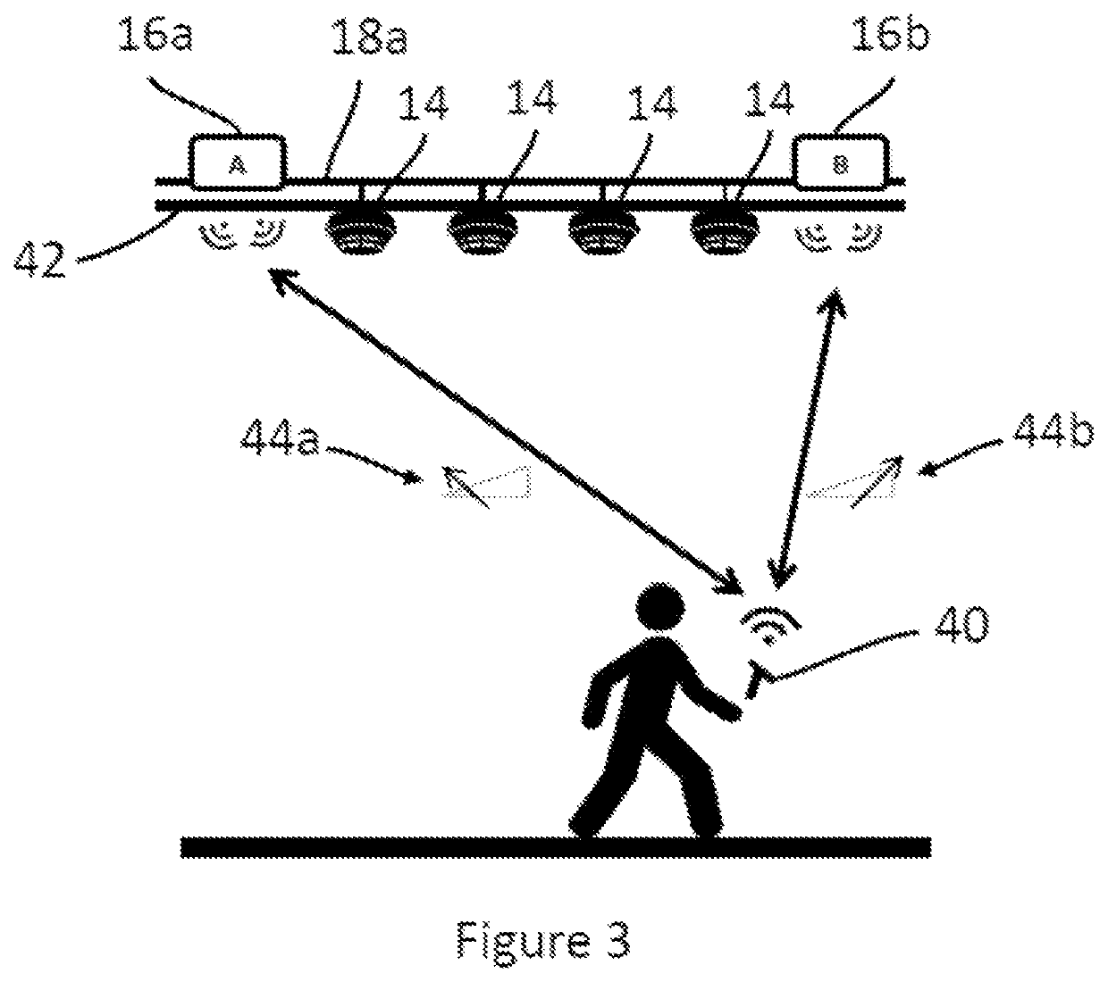
The patent text describes the use of wireless communication to make it easier to communicate and control a short-circuit isolator. This means that the isolator can be located by monitoring the strength of a wireless signal transmitted by a module as it is moved around. This helps to make maintenance and repair easier.

Problems solved by technology

This can make identification and rectification of a short circuit difficult.
However, the precise physical locations of these components may not be readily known (for example, the fire control panel will often only know a general location of the components, such as the floor of the building where the components are located).

Method used


Image

  • Short-circuit isolator
  • Short-circuit isolator

Examples


Embodiment Construction

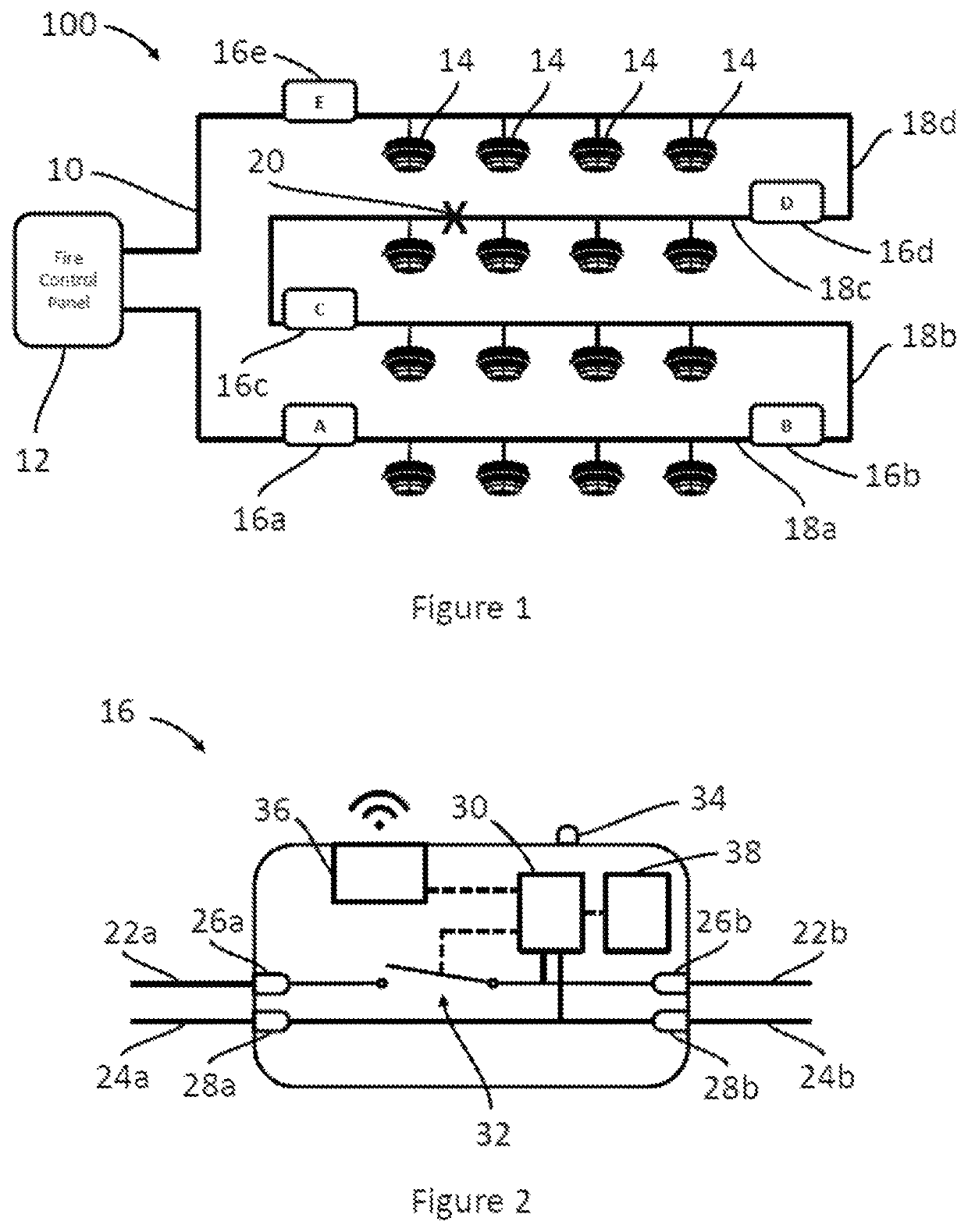
[0031]FIG. 1 is a schematic diagram illustrating power-transmission wiring 10 within a fire protection system 100.

[0032]The fire protection system 100 comprises a fire control panel 12 and a plurality of fire detectors 14, which in this example are illustrated as smoke sensors. The fire detectors 14 are electrically connected to the fire control panel 12 in a loop configuration, with the wiring 10 of the loop starting and finishing at the fire control panel 12.

[0033]The wiring 10 comprises a plurality of short-circuit isolators 16a-16e, which divide the wiring into a plurality of electrically-isolatable segments 18a-18d. In the event that a short circuit 20 occurs, for example due to an electrical fault, then the short-circuit isolators 16c, 16d on either side of the short circuit 20 will activate and electrically isolate the segment 18c containing the short circuit 20.

[0034]In one example, if a short circuit 20 were to occur at an exemplary location X, then short-circuit isolators ...


PUM


Abstract

A short-circuit isolator for electrically isolating a short circuit in a fire protection system includes a wireless communication module. The wireless communication module may transmit a status of short-circuit isolator and / or additional data that can be detected by a tool carried by an operator. The wireless communication module may additionally allow the operator to locate the short-circuit isolator, based on an intensity of a wireless signal from the wireless communication module.

Description

FOREIGN PRIORITY[0001]This application claims priority to European Patent Application No. 19382992.6, filed Nov. 13, 2019, and all the benefits accruing therefrom under 35 U.S.C. § 119, the contents of which in its entirety are herein incorporated by reference.TECHNICAL FIELD OF INVENTION[0002]The present disclosure relates to a short-circuit isolator for use in a fire protection system.BACKGROUND OF THE INVENTION[0003]Fire protection systems typically comprise a large number of electrical components, including fire detectors (such as smoke and heat sensors), manual call points, fire alarms, and fire suppression systems (such as sprinklers, fire barriers, smoke extractors, etc.). These are typically electrically connected in a loop configuration, with the connecting wiring starting and finishing at a fire control panel. In some instances, multiple loops may be connected to a single fire control panel, and a loop may sometimes comprise one or more short spurs.[0004]A loop configurati...

Claims


Application Information

Patent Timeline
Patent Type & Authority Patents(United States)
IPC IPC(8): G08B21/18H04B17/27G01R31/52A62C37/50G08B17/00H02H3/04H02H3/08
CPCG08B21/185A62C37/50G01R31/52G08B17/00H02H3/04H02H3/08H04B17/27G08B25/04G08B29/06G08B29/123
Inventor CORDOBA GALERA, ANDRES
Owner CARRIER CORP
Learn More