Unified bus architecture for PoE communication and control
a communication and control technology, applied in the field of power over ethernet, can solve the problems of high cost and complex implementation, and achieve the effects of significant savings both in cost and complexity, and simplified communication and control
- Summary
- Abstract
- Description
- Claims
- Application Information
AI Technical Summary
Benefits of technology
Problems solved by technology
Method used
Image
Examples
embodiment 500
[0045]The above described communication and control architectures can also be extended to a chassis-based or a stackable-based switch implementation, in which a centralized CPU / Controller located in a supervisory slot of the chassis / stackable-based switch controls one or more Ethernet and / or PoE linecards / stackable units located on different slots of the chassis / stackable-based switch. A chassis-based implementation 500 is illustrated in FIG. 5. As shown in FIG. 5, chassis-based switch 502 includes a supervisory slot 504a and a plurality of linecard slots 504b-n. Supervisory slot 504a contains a centralized CPU / Controller 512. In another embodiment, chassis-based switch 502 also includes a backup supervisory slot containing a backup CPU / Controller. Line card slots 504b-n each contains a respective Ethernet or PoE linecard. For example, in embodiment 500, linecard slots 504-n respectively contain PoE linecards 302b-n. As above, PoE linecard 302 includes a PHY / Data subsystem 310 and a...
embodiment 600
[0050]FIG. 6 illustrates a unified communication and control bus architecture 600 according to an embodiment of the present invention. Embodiment 600 will be described with reference to a chassis-based switch implementation, but can be readily implemented in a stackable-based switch implementation (i.e., pizza box implementation).
[0051]As shown in FIG. 6, chassis-based switch 602 includes a supervisory slot 604a and a plurality of linecard slots 604b-n. As in implementation 500, supervisory slot 604a includes a centralized CPU / Controller 512, and linecard slots 604b-n each includes a respective Ethernet and / or PoE linecard 302. In contrast to implementation 500, however, architecture 600 uses a single bus 606 for communication and control between centralized CPU / Controller 512 and PHY / Data subsystems 310b-n and PoE subsystems 312b-n on linecards 302b-n.
[0052]According to embodiment 600, full isolation is implemented between centralized CPU / Controller 512 and linecards 302b-n. In an...
embodiment 700
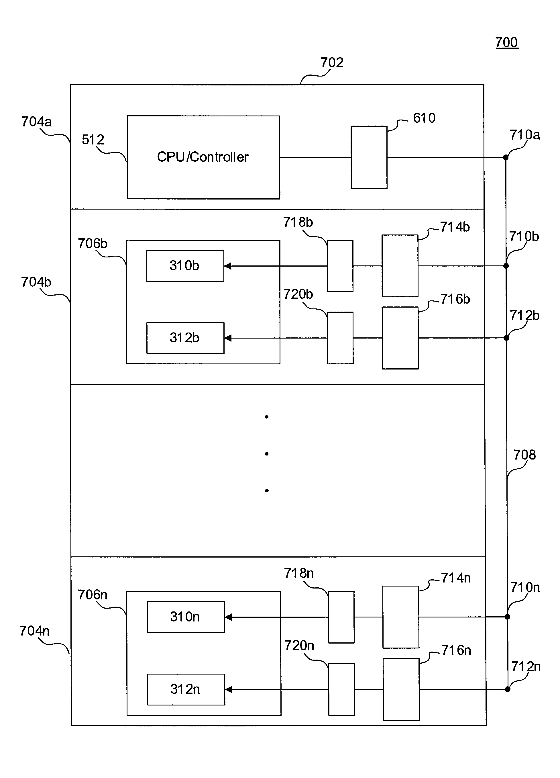
[0061]Embodiment 700 will be described with reference to a chassis-based switch implementation, but can be readily implemented in a stackable-based switch implementation (i.e., pizza box implementation).
[0062]Embodiment 700 is similar to embodiment 600 described above in that it also uses full isolation between CPU / Controller 512 and linecards 706b-n of chassis-based switch 702. However, as shown in FIG. 7, embodiment 700 uses two bus tap points 710 and 712 per linecard slot 704. As such, in an embodiment, two re-referencing circuits 714 and 716 are used for each linecard slot 704, in order to re-reference the output of CPU / Controller 512 from the logic environment of CPU / Controller 512 to logic environments compatible with PHY / Data subsystem 310 and PoE subsystem 312, respectively. Similarly, two bus controller subsystems 718 and 720 are used per linecard slot 704, with each bus controller subsystem dedicated to either PHY / Data subsystem 310 or PoE subsystem 312.
[0063]In an embodim...
PUM
 Abstract
Description
Claims
Application Information
 - R&D
- Intellectual Property
- Life Sciences
- Materials
- Tech Scout
- Unparalleled Data Quality
- Higher Quality Content
- 60% Fewer Hallucinations
Browse by: Latest US Patents, China's latest patents, Technical Efficacy Thesaurus, Application Domain, Technology Topic, Popular Technical Reports.
© 2025 PatSnap. All rights reserved.Legal|Privacy policy|Modern Slavery Act Transparency Statement|Sitemap|About US| Contact US: help@patsnap.com


