Electronic device and touch detection method

a technology of touch detection and electronic devices, applied in the direction of electric digital data processing, instruments, computing, etc., can solve the problem that the conventional structure is not yet able to achieve multiple integrated applications

Active Publication Date: 2022-07-05
TPK ADVANCED SOLUTIONS
View PDF6 Cites 1 Cited by
  • Summary
  • Abstract
  • Description
  • Claims
  • Application Information

AI Technical Summary

Problems solved by technology

However, the light transmittance of this conventional structure needs to be improved, so the conventional structure is not yet able to achieve multiple integrat...

Method used


Image

  • Electronic device and touch detection method
  • Electronic device and touch detection method
  • Electronic device and touch detection method

Examples


Embodiment Construction

[0026]Reference will now be made in detail to the present embodiments of the disclosure, examples of which are illustrated in the accompanying drawings. Wherever possible, the same reference numbers are used in the drawings and the description to refer to the same or like parts. However, specific structural and functional details disclosed herein are merely representative for purposes of describing example embodiments, and thus may be embodied in many alternate forms and should not be construed as limited to only example embodiments set forth herein. Therefore, it should be understood that there is no intent to limit example embodiments to the particular forms disclosed, but on the contrary, example embodiments are to cover all modifications, equivalents, and alternatives falling within the scope of the disclosure.

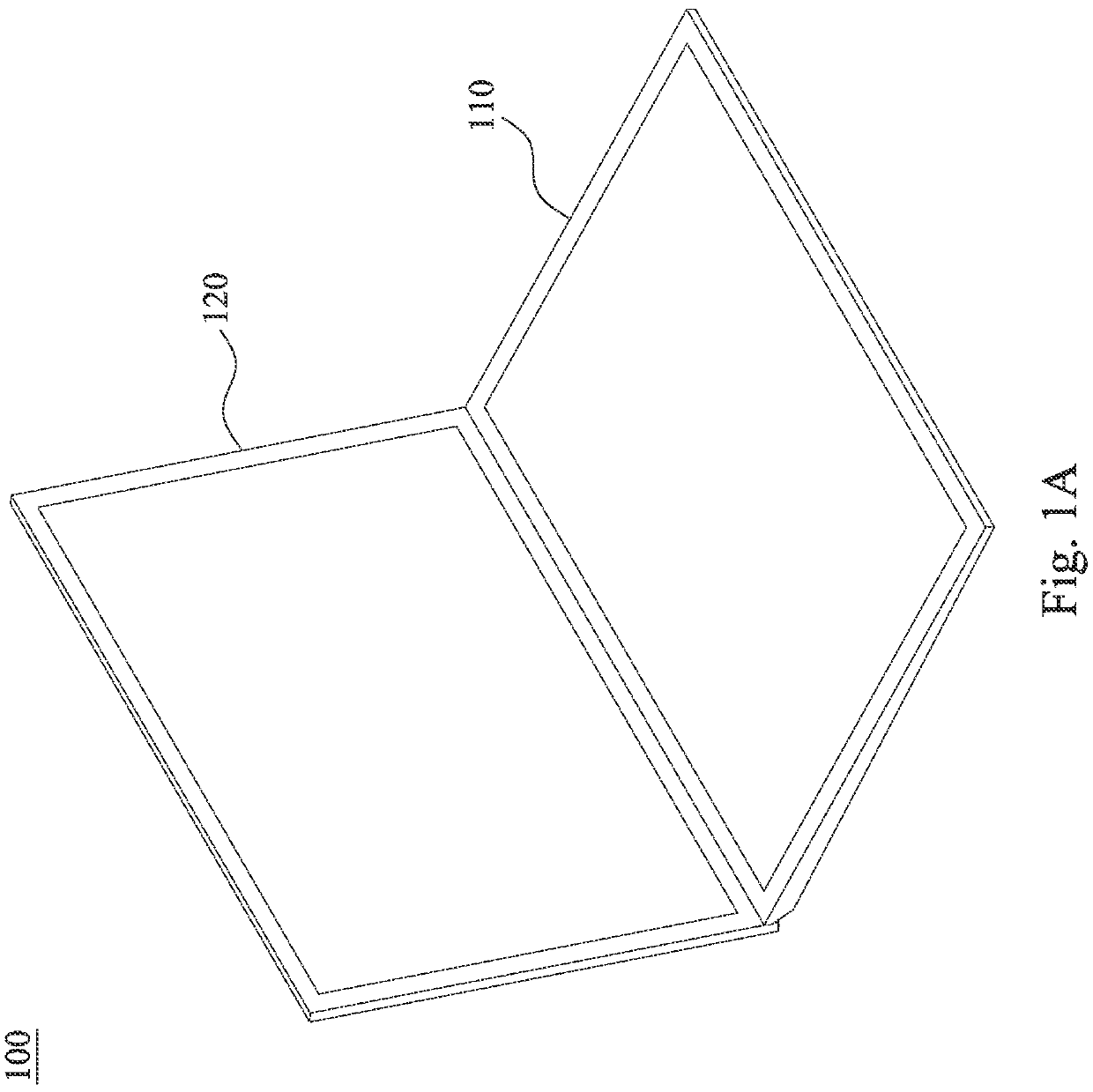
[0027]Reference is made to FIG. 1A. FIG. 1A is a schematic diagram showing an electronic device 100 according to an embodiment of the present disclosure. As shown in FIG. ...


PUM


Abstract

An electronic device includes a touch module, a display module, and a control module. The touch module is configured to detect a touch input. The display module is disposed under the touch module. The control module is electrically connected to the touch module and the display module and configured to: detect a contact area of the touch input on the touch module; make the display module display a first input interface when the contact area is greater than a first threshold area; and make the display module display a second input interface when the contact area is smaller than a second threshold area, in which the second threshold area is equal to or smaller than the first threshold area.

Description

BACKGROUNDTechnical Field[0001]The present disclosure relates to an electronic device and a touch detection method.Description of Related Art[0002]As the demand for touch pressure sensing applications has greatly increased, related integrated applications have emerged accordingly. In response to mobile needs, products equipped with applications with touch sensing, pressure sensing, and display functions have attracted attention.[0003]Some existing art (for example, Chinese Patent Application Publication No. CN106557212A) uses a pressure-sensitive composite structure with conductive particles sandwiched between two electrodes, and uses impedance to perform pressure interpretation. However, the light transmittance of this conventional structure needs to be improved, so the conventional structure is not yet able to achieve multiple integrated applications (for example, requirements of being equipped with a stylus, being touched by fingers, being foldable, having high light transmittanc...

Claims


Application Information

Patent Timeline
IPC IPC(8): G06F3/041G06F3/044
CPCG06F3/04166G06F3/0445G06F2203/04105G06F2203/04106G06F2203/04107
Inventor LEE, LIEN HSINCHAN, YU TINGCHENG, TAI SHIH
Owner TPK ADVANCED SOLUTIONS
Why Eureka
Try Eureka