Waveguide device and optical engine

a waveguide and optical engine technology, applied in the direction of optical waveguide light guide, instruments, optics, etc., can solve the problems of low waveguide efficiency and light cannot be reflected in the waveguide based, and achieve the effect of efficient solving the aforementioned problems

Active Publication Date: 2020-07-02
HTC CORP
View PDF0 Cites 1 Cited by
  • Summary
  • Abstract
  • Description
  • Claims
  • Application Information

AI Technical Summary

Benefits of technology

[0006]An aspect of the disclosure is to provide a waveguide device and an optical engine that can efficiently solve the aforementioned problems.

Problems solved by technology

As this is still an emerging technology, there are certain challenges associated with utilizing waveguides to display images of virtual objects to a user.
However, if the diffraction angle of the light of a certain wavelength is smaller than a critical angle of the waveguide, the light cannot be reflected in the waveguide based on the principle of total reflection and will transmit out of the waveguide.
As a result, the efficiency of the waveguide is low.
Accordingly, it is an important issue for the industry to provide an optical engine capable of solving the aforementioned problems.

Method used


Image

  • Waveguide device and optical engine
  • Waveguide device and optical engine
  • Waveguide device and optical engine

Examples


Embodiment Construction

[0026]Reference will now be made in detail to the present embodiments of the disclosure, examples of which are illustrated in the accompanying drawings. Wherever possible, the same reference numbers are used in the drawings and the description to refer to the same or like parts. However, specific structural and functional details disclosed herein are merely representative for purposes of describing example embodiments, and thus may be embodied in many alternate forms and should not be construed as limited to only example embodiments set forth herein. Therefore, it should be understood that there is no intent to limit example embodiments to the particular forms disclosed, but on the contrary, example embodiments are to cover all modifications, equivalents, and alternatives falling within the scope of the disclosure.

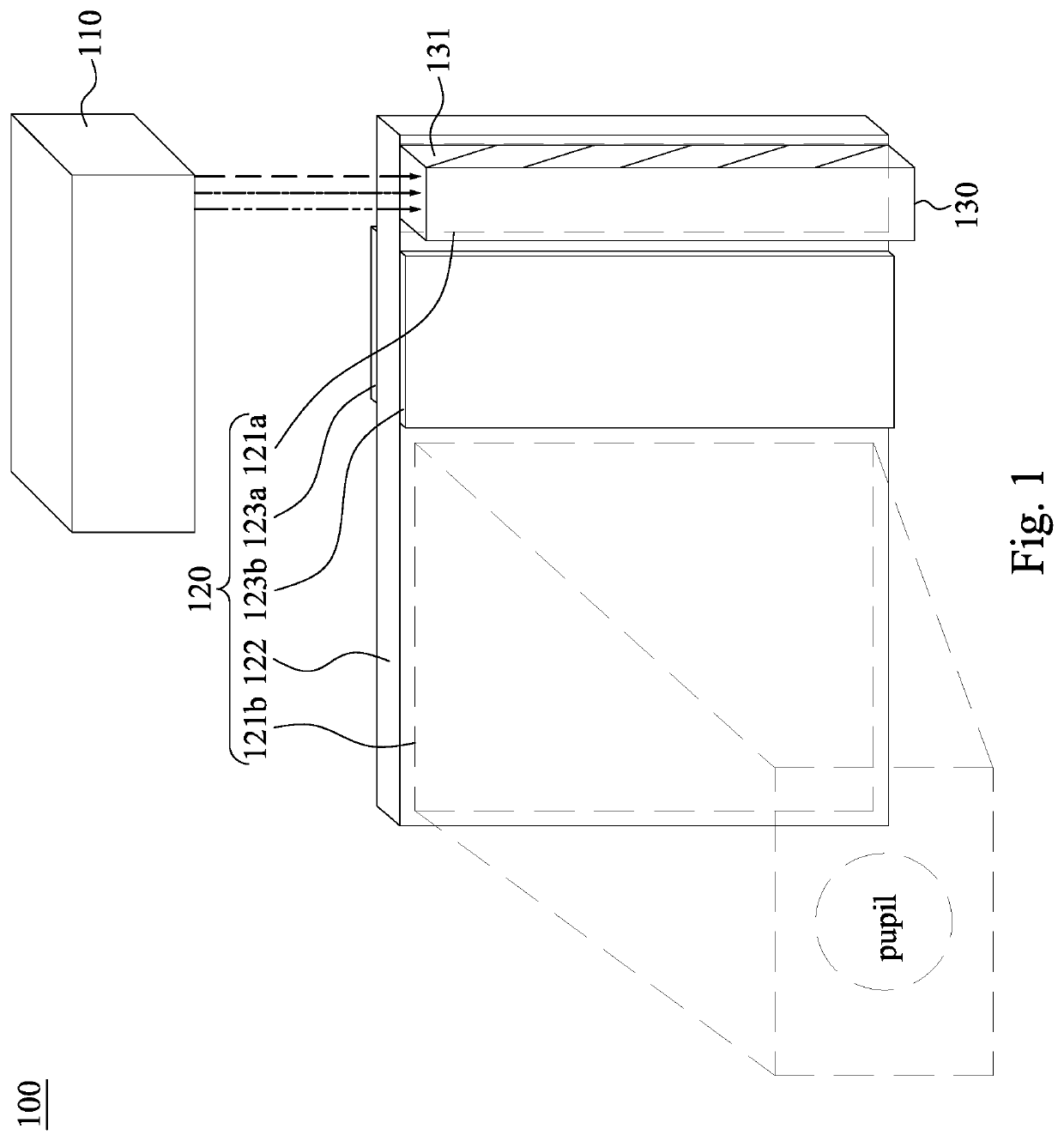
[0027]Reference is made to FIG. 1. FIG. 1 is a schematic view of an optical engine 100 according to some embodiments of the present disclosure. As shown in FIG. 1, the opt...


PUM

PropertyMeasurementUnit
wavelength bandaaaaaaaaaa

Abstract

A waveguide device includes two diffractive optical elements, a waveguide element, and two polarizing units. Each of the diffractive optical elements has a grating configured to diffract light of a wavelength to propagate with a diffraction angle. The waveguide element is configured to guide light propagated from one of the diffractive optical elements to the other of the diffractive optical elements. The polarizing units are at opposite surfaces of the waveguide element and optically coupled between the diffractive optical elements. Each of the polarizing units is configured to reflect light of a first polarization characteristic and transmit light of a second polarization characteristic.

Description

CROSS-REFERENCE TO RELATED APPLICATION[0001]This application claims priority to U.S. Provisional Application Ser. No. 62 / 787,392, filed on Jan. 2, 2019, which is herein incorporated by reference.BACKGROUNDTechnical Field[0002]The present disclosure relates to a waveguide device and an optical engine.Description of Related Art[0003]Various types of computing, entertainment, and / or mobile devices can be implemented with a transparent or semi-transparent display through which a user of a device can view the surrounding environment. Such devices, which can be referred to as see-through, mixed reality display device systems, or as augmented reality (AR) systems, enable a user to see through the transparent or semi-transparent display of a device to view the surrounding environment, and also see images of virtual objects (e.g., text, graphics, video, etc.) that are generated for display to appear as a part of, and / or overlaid upon, the surrounding environment. These devices, which can be ...

Claims


Application Information

Patent Timeline
Patent Type & Authority Applications(United States)
IPC IPC(8): G02B6/10G02B5/18G02B27/01
CPCG02B6/105G02B27/0172G02B2027/0174G02B5/1814G02B6/00G02B27/0101G02B2027/0178G02B6/0028G02B27/0018
Inventor DENG, QING-LONG
Owner HTC CORP
Why Eureka
Try Eureka