Enhanced acoustic detection of gas leaks in underground gas pipelines

a technology of acoustic detection and underground gas pipeline, which is applied in the direction of fluid tightness measurement, instruments, machines/engines, etc., can solve the problems of significant gas leakage from underground gas pipelines, difficult to pinpoint the location of such leakage, and loss of revenues

Inactive Publication Date: 2004-04-27
GAS TECH INST
View PDF19 Cites 130 Cited by
  • Summary
  • Abstract
  • Description
  • Claims
  • Application Information

AI Technical Summary

Problems solved by technology

Gas leaks from underground gas pipelines are a significant problem in terms of both the amount of revenues lost to gas companies and the potential hazards presented.
The locations of such leaks are also very difficult to pinpoint, particularly when the gas has migrated beneath pavement or frozen ground, when the gas has spread over a large area, when multiple leaks are present, or when the water table is high and gas and air are displaced from the ground.
Leaks from low-pressure (6-12 inches of water column; 1/4 to 1/2 psig) cast-iron pipelines are often particularly difficult to pinpoint using current technology, such as a combustible gas indicator.
Previous efforts to improve the sensitivity of sonic detectors

Method used


Image

  • Enhanced acoustic detection of gas leaks in underground gas pipelines
  • Enhanced acoustic detection of gas leaks in underground gas pipelines
  • Enhanced acoustic detection of gas leaks in underground gas pipelines

Examples


Embodiment Construction

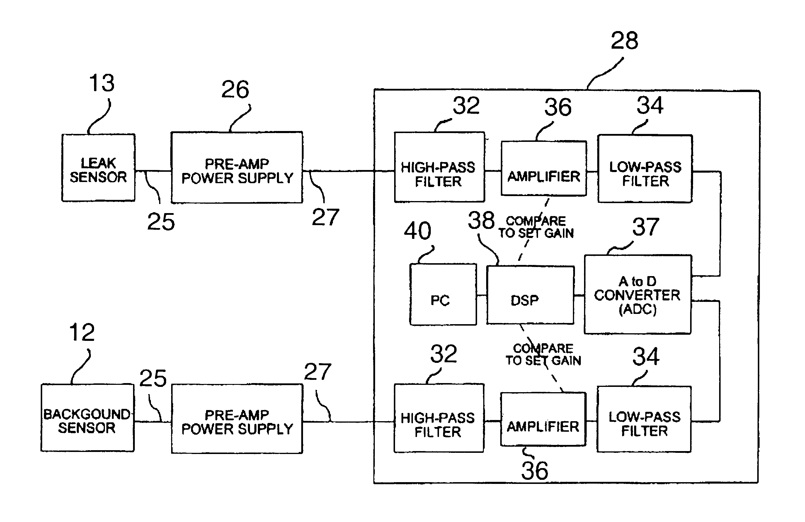
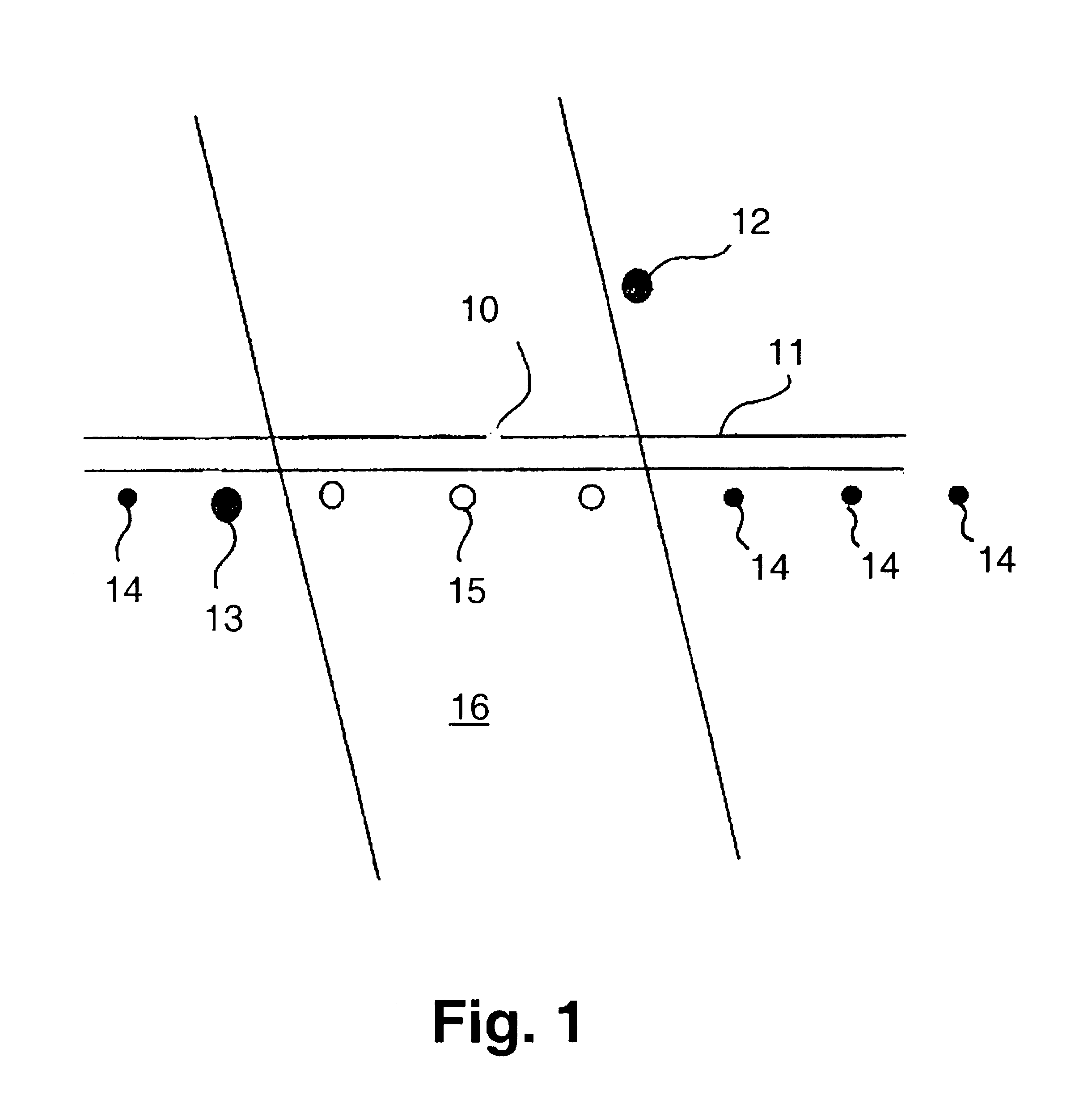
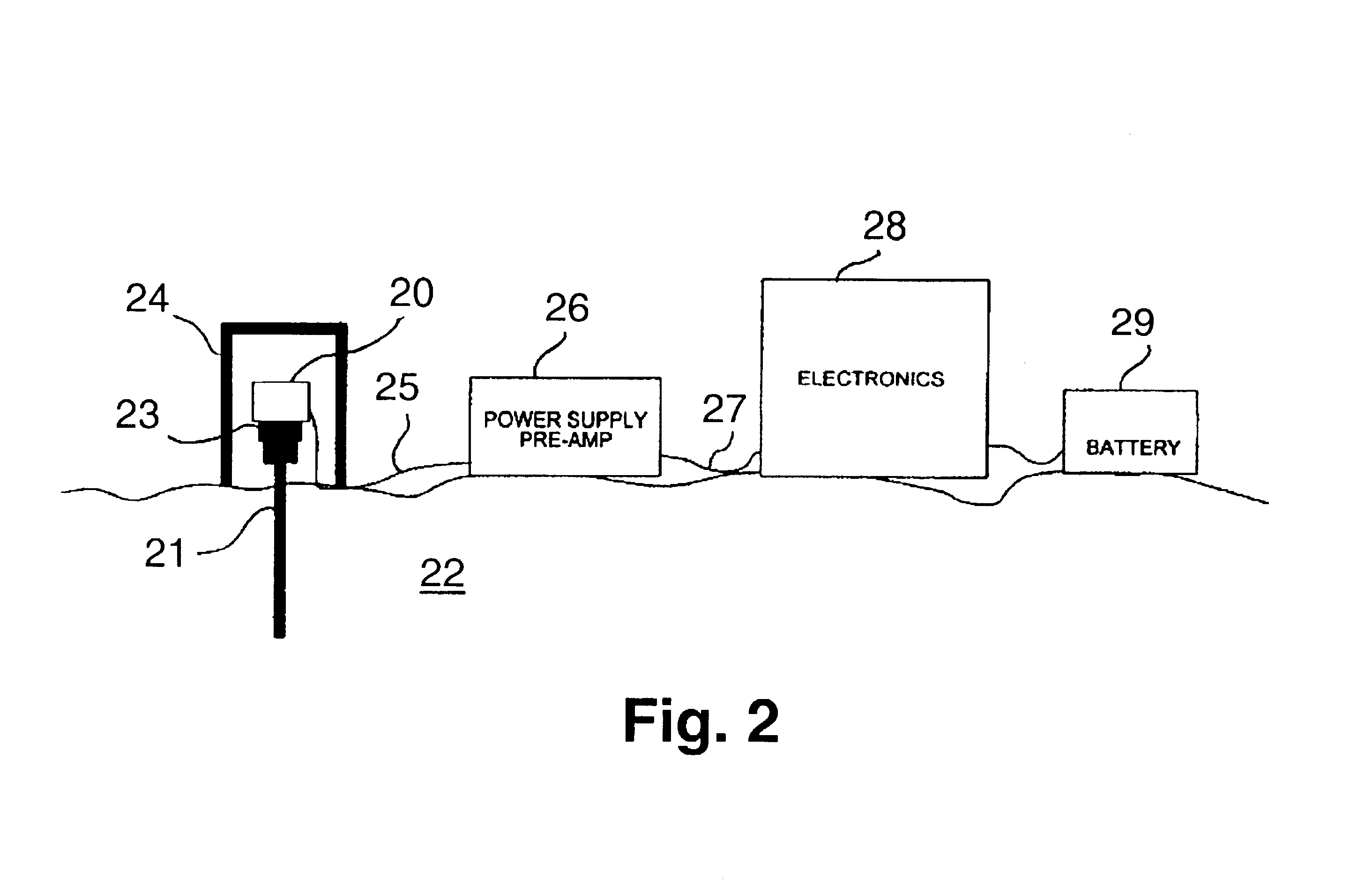
In accordance with one embodiment of this invention, two acoustic sensors are used to determine the location of gas leaks from underground gas pipelines. Preferred acoustic sensors for use in the method of this invention are selected from the group consisting of accelerometers, including optical fiber accelerometers, velocity sensors, geophones and combinations thereof. Amplifiers employed in the acoustic sensors should be as low as possible in thermal noise. In accordance with a particularly preferred embodiment, an accelerometer having a resonant frequency in the range of about 900 to about 2500 Hz is used. Soil normally attenuates most of the leak sound at frequencies higher than about 3000 Hz. Typically, the accelerometer does not need to be responsive to frequencies below about 100 Hz although, to achieve a minimum noise floor, it may be. Suitable accelerometers for use in this invention may be obtained from Wilcoxon Research, Inc. in Gaithersburg, Md. and PCB Piezotronics in D...


PUM


Abstract

A method for locating gas leaks from underground gas pipelines in which a first acoustic sensor having a first signal output is positioned in ground disposed substantially above or at a distance from the underground gas pipeline. At least one second acoustic sensor having a second signal output is positioned in the ground at a plurality of locations substantially above the underground gas pipeline. The output signals from the acoustic sensors are measured for each location of the second acoustic sensor and the signals are adaptively filtered to remove common noise signal components. The statistical minima of these rms voltages are determined for both the first output signal and the adaptively filtered second output signals and the differences determined. The location of the second acoustic sensor corresponding to the largest positive said difference is the location closest to the leak site.

Description

1. Field of the InventionThis invention relates to a method and apparatus for locating gas leaks from underground gas-containing pipelines by acoustic means. More particularly, this invention relates to the use of acoustic sensors for pinpointing the location of a gas leak from an underground gas pipeline so as to avoid unnecessary excavation of the ground surrounding the pipeline.2. Description of Related ArtGas leaks from underground gas pipelines are a significant problem in terms of both the amount of revenues lost to gas companies and the potential hazards presented. The locations of such leaks are also very difficult to pinpoint, particularly when the gas has migrated beneath pavement or frozen ground, when the gas has spread over a large area, when multiple leaks are present, or when the water table is high and gas and air are displaced from the ground. Leaks from low-pressure (6-12 inches of water column; 1 / 4 to 1 / 2 psig) cast-iron pipelines are often particularly difficult ...

Claims


Application Information

Patent Timeline
IPC IPC(8): G01N29/00G01M3/24
CPCG01M3/243
Inventor HUEBLER, JAMES EMERSONZIOLKOWSKI, CHRISTOPHER JOHN
Owner GAS TECH INST
Why Eureka
Try Eureka