

Physics processing unit instruction set architecture
- Summary
- Abstract
- Description
- Claims
- Application Information
AI Technical Summary
Benefits of technology
Problems solved by technology
Method used
Image

Examples
Embodiment Construction
)
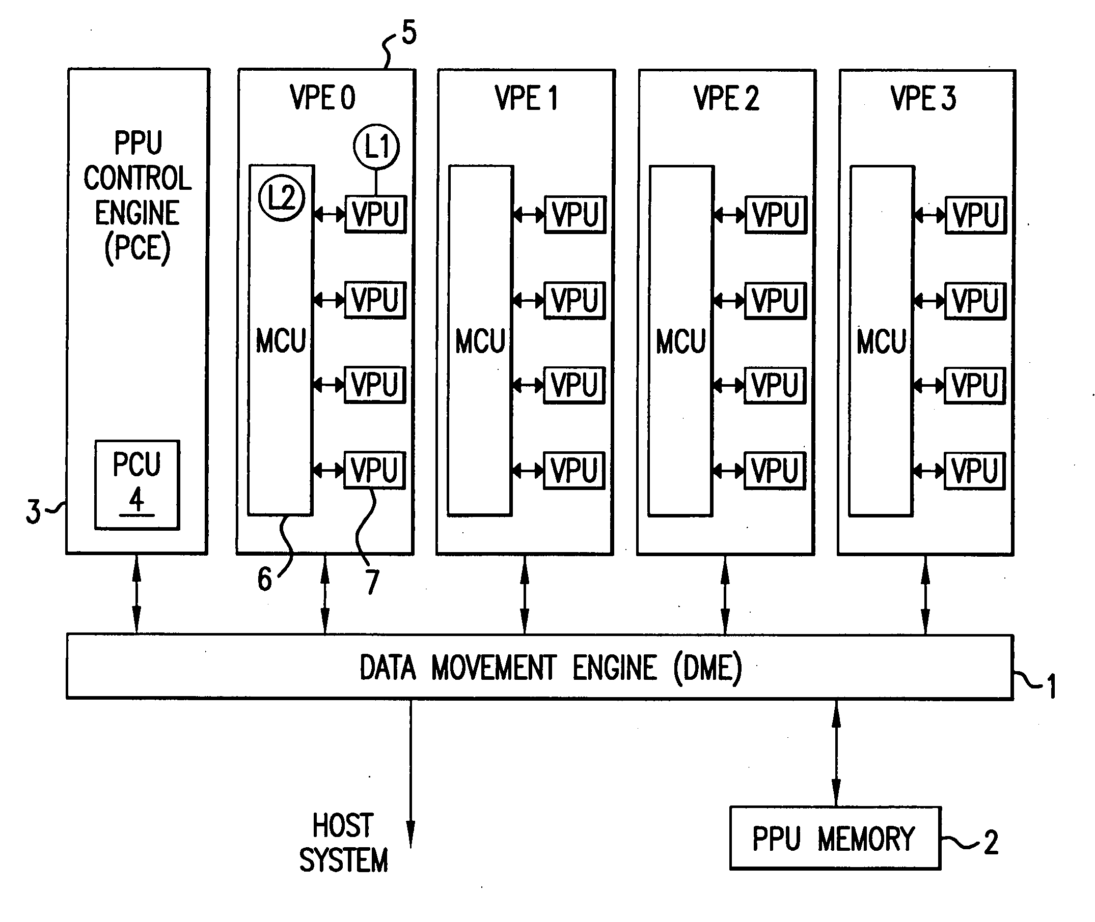
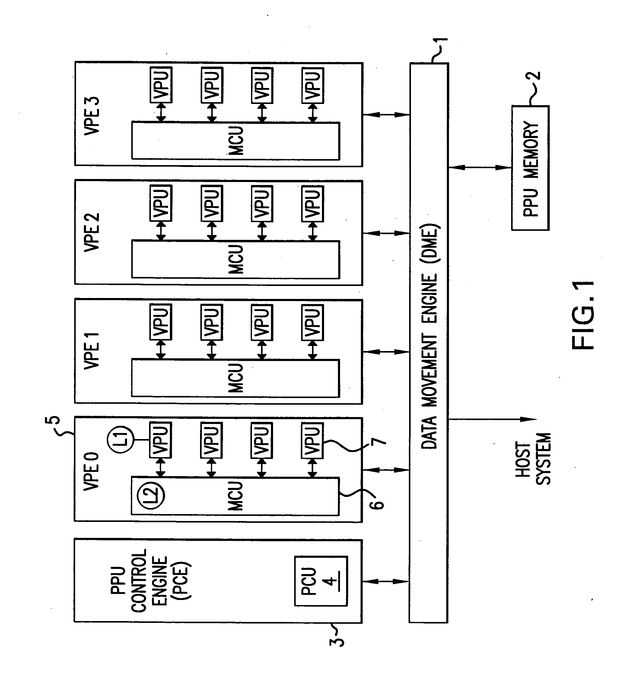
[0021] The present invention will now be described in the context of one or more preferred embodiments. These embodiments describe in one aspect an integrated chip architecture that balances expanded parallelism with control programming efficiency.
[0022] Expanded parallelism, while facilitating data processing speed, requires some careful additional consideration in its impact on programming overhead. For example, some degree of networking is required to coordinate the transfer of data to, and the operation of multiple independent vector processors. This networking requirement adds to the programming burden. The use of Very Long Instruction Words (VLIWs) also increases programming complexity. Multi-threading data transfers and multiple thread execution further complicate programming.
[0023] Thus, the material advantages afforded by a hardware architecture specifically tailored to efficiently transfer physics data and to execute the mathematical / logic operations required to resolve...
PUM
 Abstract
Description
Claims
Application Information