Light guide plate and backlight module

a technology of backlight module and light guide plate, which is applied in the direction of planar/plate-like light guide, lighting and heating apparatus, instruments, etc., can solve the problems of uneven surface light source, hot spot worsening, and plate may not be able to provide uniform surface, etc., and achieve the effect of effectively solving the problem of hot spo

Inactive Publication Date: 2012-07-24
CORETRONIC
View PDF3 Cites 29 Cited by
  • Summary
  • Abstract
  • Description
  • Claims
  • Application Information

AI Technical Summary

Benefits of technology

[0008]Accordingly, the invention is directed to a light guide plate able to effectively resolve the problem of hot spot.
[0012]As described above, the embodiment or the embodiments of the invention may have at least one of the following advantages. In the light guide plate according to the embodiment of the invention, a plurality of optical structures is disposed, and the first TIR surface, the second TIR surface, and the third TIR surface of each of the optical structures are disposed within a specific angle range so that a part of the light beams from the incident surface is totally internally reflected by any adjacent two of the first TIR surface, the second TIR surface, and the third TIR surface in sequence. Accordingly, the optical structures allow the part of the light beams to bounce back to the areas in the light guide plate and the areas close to the incident surface are at both sides of the optical axes of the light emitting devices, so that the problem of hot spot may be effectively resolved and the uniformity of the surface light source provided by a backlight module using the light guide plate may be improved.

Problems solved by technology

The light guide plate may not be able to provide a uniform surface light source due to the existence of these bright and dark regions, and this is referred to as the “hot spot” phenomenon.
As a result, the surface areas of the dark regions are increased, and accordingly the surface light source becomes even more uneven and the problem of hot spot is worsened.

Method used


Image

  • Light guide plate and backlight module
  • Light guide plate and backlight module
  • Light guide plate and backlight module

Examples


first embodiment

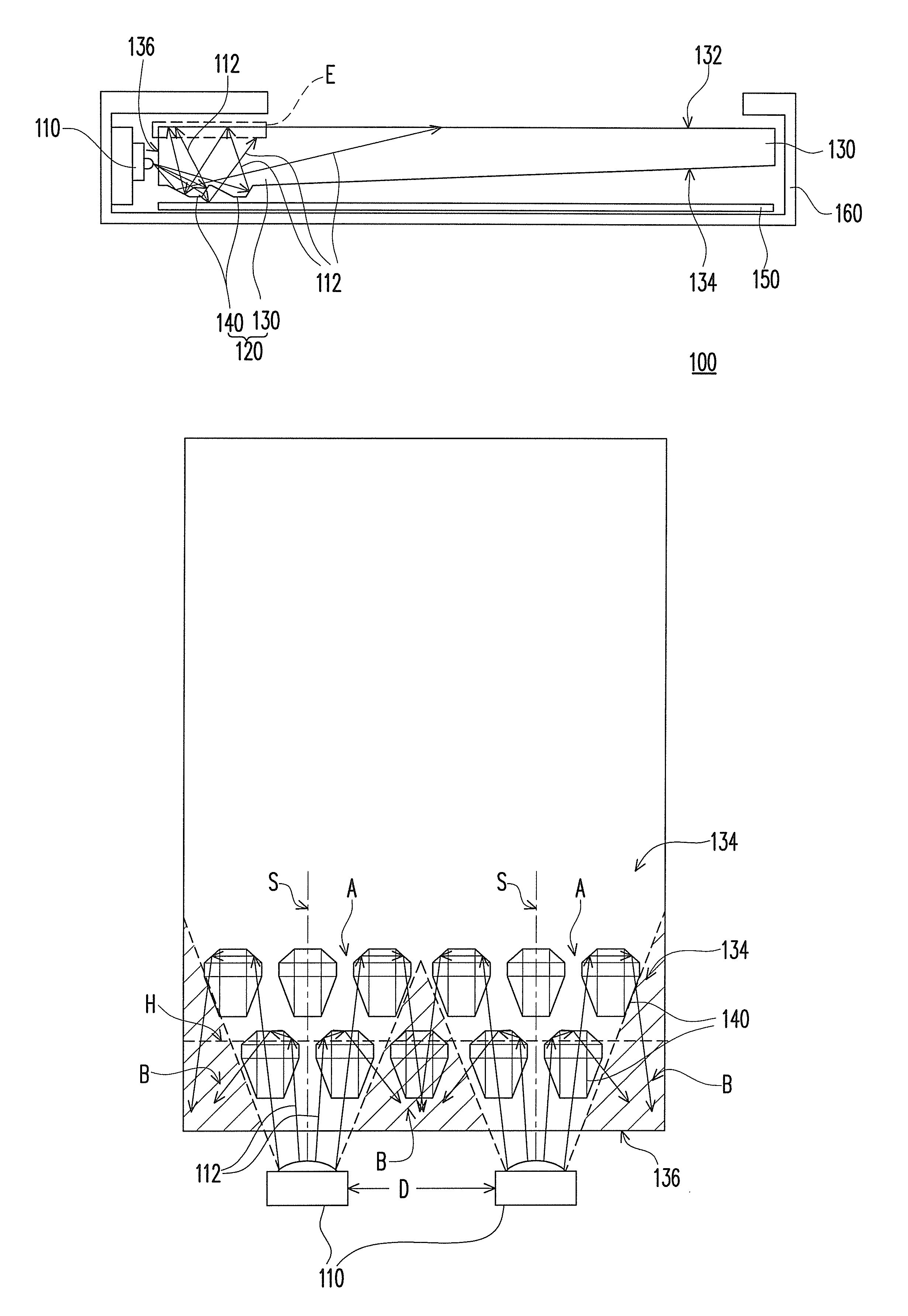
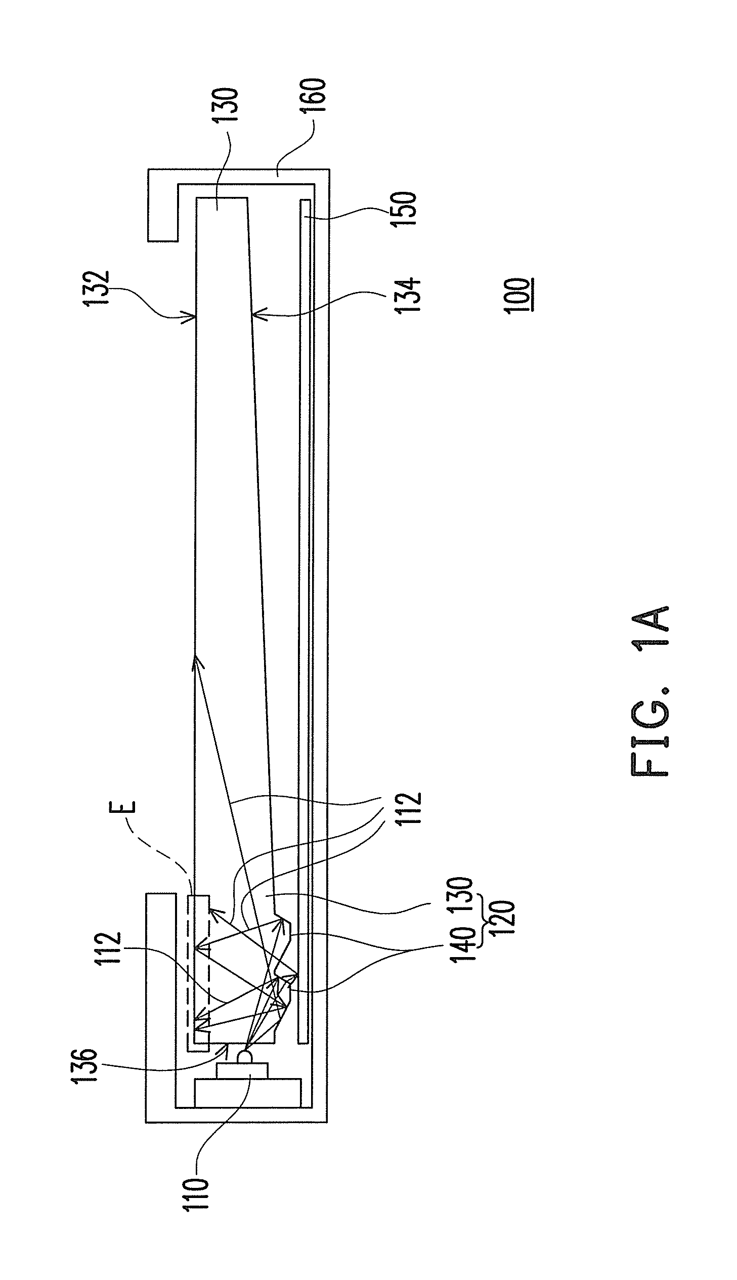
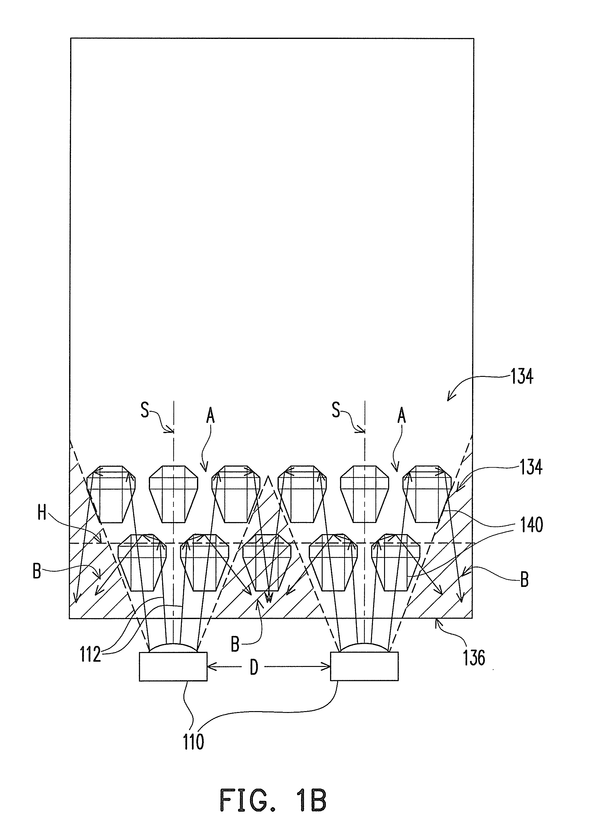
[0033]Referring to FIG. 1A, FIG. 1B, and FIG. 2A, in the embodiment, the backlight module 100 includes a plurality of light emitting devices 110 (two are illustrated in FIG. 1B) and a light guide plate 120. Each of the light emitting devices 110 is capable of emitting a light beam 112. In the embodiment, each of the light emitting devices 110 may be a light emitting diode (LED). The light guide plate 120 is disposed in the transmission path of the light beams 112 and is capable of guiding the light beams 112 emitted by the light emitting devices 110. The light guide plate 120 includes a light-transmissive substrate 130 and a plurality of optical structures 140. The light-transmissive substrate 130 has a first surface 132, a second surface 134 opposite to the first surface 132, and an incident surface 136 connecting the first surface 132 and the second surface 134. In the embodiment, the light emitting devices 110 are disposed beside the incident surface 136 of the light-transmissive...

second embodiment

[0043]Referring to FIGS. 6A-6D, the backlight module in the embodiment is similar to the backlight module 100 described above (as illustrated in FIG. 1A and FIGS. 2A˜2D), and the difference between the two is described herein. In an optical structure 140′ of the embodiment, a first normal vector V1′ of a first TIR surface 142′ passing through the geometric center C1′ of the first TIR surface 142′ forms an angle θ1′ with the second surface 134, wherein the dotted line D1′ is parallel to the second surface 134. A second normal vector V2′ of a second TIR surface 144′ passing through the geometric center C2′ of the second TIR surface 144′ forms an angle θ2′ with the second surface 134, wherein the dotted line D2′ is parallel to the second surface 134. A third normal vector V3′ of the third TIR surface 146′ passing through the geometric center C3′ of the third TIR surface 146′ forms an angle θ3′ with the second surface 134, wherein the dotted line D3′ is parallel to the second surface 13...

third embodiment

[0044]Referring to FIG. 7, the backlight module in the embodiment is similar to the backlight module 100 described above (as illustrated in FIGS. 1A and 2A), and the difference between the two is described herein. In the backlight module provided by the embodiment, at least parts of the orthogonal projection vectors U1″ of the first normal vectors V1″ of the first TIR surfaces 142″ of the optical structures 140″ on the second surface 134 are not parallel to each other, at least parts of the orthogonal projection vectors U2″ of the second normal vectors V2″ of the optical structures 140″ on the second surface 134 are not parallel to each other, and at least parts of the orthogonal projection vectors U3″ of the third normal vectors V3″ of the optical structures 140″ on the second surface are not parallel to each other. In other words, compared with the above backlight module 100 in which the orthogonal projection vectors U1, U2, and U3 of the optical structures 140 are disposed toward...


PUM


Abstract

A light guide plate capable of guiding a light beam from a light emitting device and a backlight module using the light guide plate are provided. The light guide plate includes a light-transmissive substrate and optical structures. The light-transmissive substrate has a first surface, an opposite second surface, and an incident surface connecting the first and the second surface. The light beam enters the light-transmissive substrate through the incident surface and is emitted out of the light-transmissive substrate through the first surface. The optical structures are disposed on the second surface. Each optical structure has a first total internal reflection (TIR) surface, a second TIR surface, and a third TIR surface. The second TIR surface connects the first and third TIR surfaces. Part of the light beam from the incident surface is totally internally reflected by any adjacent two of the first, second, and third TIR surfaces in sequence.

Description

CROSS-REFERENCE TO RELATED APPLICATION[0001]This application claims the priority benefit of Taiwan application serial no. 98116017, filed on May 14, 2009. The entirety of the above-mentioned patent application is hereby incorporated by reference herein and made a part of specification.BACKGROUND OF THE INVENTION[0002]1. Field of the Invention[0003]The invention generally relates to an optical device and a backlight module, and more particularly, to a light guide plate and a side type backlight module.[0004]2. Description of Related Art[0005]In recent years, liquid crystal display (LCD) has been broadly applied in our daily life along with the rapid development of flat panel display techniques. LCD has gradually replaced the conventional cathode ray tube (CRT) due to its many advantages such as light weight, small volume, low power consumption, and small thickness.[0006]An LCD has a liquid crystal panel and a backlight module, wherein the backlight module is disposed behind the liqui...

Claims


Application Information

Patent Timeline
Patent Type & Authority Patents(United States)
IPC IPC(8): F21V7/04
CPCG02B6/0018G02B6/0068
Inventor TENG, TUN-CHIENCHEN, JYH-MINGKUO, MING-FENGTSANG, CHIH-JEN
Owner CORETRONIC
Why Eureka
Try Eureka