
Brake monitoring system with temperature monitoring

a technology of temperature monitoring and brake monitoring system, which is applied in the direction of brake systems, brake components, transportation and packaging, etc., can solve the problems of brake drag, system not providing information to the driver regarding the efficiency of the brake system, and substantial leakage of compressed air

Active Publication Date: 2022-07-12
HALDEX BRAKE PROD CORP
View PDF38 Cites 1 Cited by
  • Summary
  • Abstract
  • Description
  • Claims
  • Application Information

AI Technical Summary

Benefits of technology

The system effectively alerts drivers to potential brake issues, preventing brake drag and temperature-related hazards, ensuring safe operation and reducing the risk of fires in heavy-duty vehicle braking systems.

Problems solved by technology

A loss of compressed air in typical air brake systems means that the power spring applies a braking force to prevent the vehicle from moving.
While this configuration will provide a functioning system in the event of catastrophic failure of the service / control line, this system will not provide information to the driver regarding the efficiency of the braking system.
For example, the service / control line may suffer from a leaky connection causing substantial leaking of the compressed air.
There may be enough air pressure in the system to allow for operation of the vehicle, but the vehicle may suffer from brake drag, meaning the air pressure is not high enough to completely overcome the power spring such that the brake is partially applied during normal driving operation.
Another problem that prior art systems face is the provision of stoplight power to the trailer when the brakes are applied.
If a braking system malfunctions, the malfunction may lead to brake drag and an associated increase in the temperature of the wheel end.
If the malfunction is not addressed, the temperature increase may lead to a fire at the wheel end.

Method used


Image

  • Brake monitoring system with temperature monitoring
  • Brake monitoring system with temperature monitoring
  • Brake monitoring system with temperature monitoring

Examples


Embodiment Construction

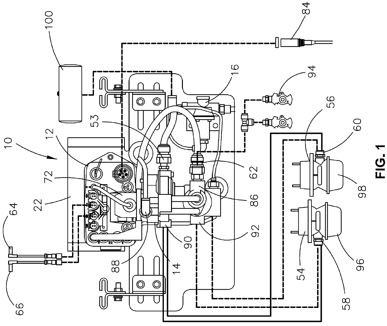
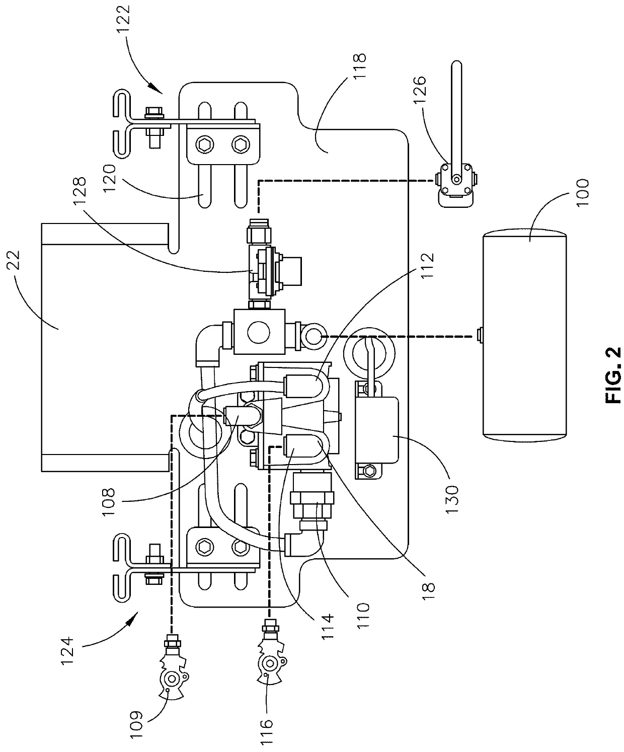
[0037]A trailer brake and monitoring system in accordance with one embodiment of the invention described herein is identified generally with the reference numeral 10 in FIG. 1. The trailer brake and monitoring system includes a trailer control module 12, a brake valve 14, a reservoir purge valve 16, a booster valve 18 (FIG. 2), a communications device 20 (FIG. 4), and a mounting bracket 22 to which the trailer control module 12, brake valve 14, reservoir purge valve 16, and booster valve 18 are mounted.

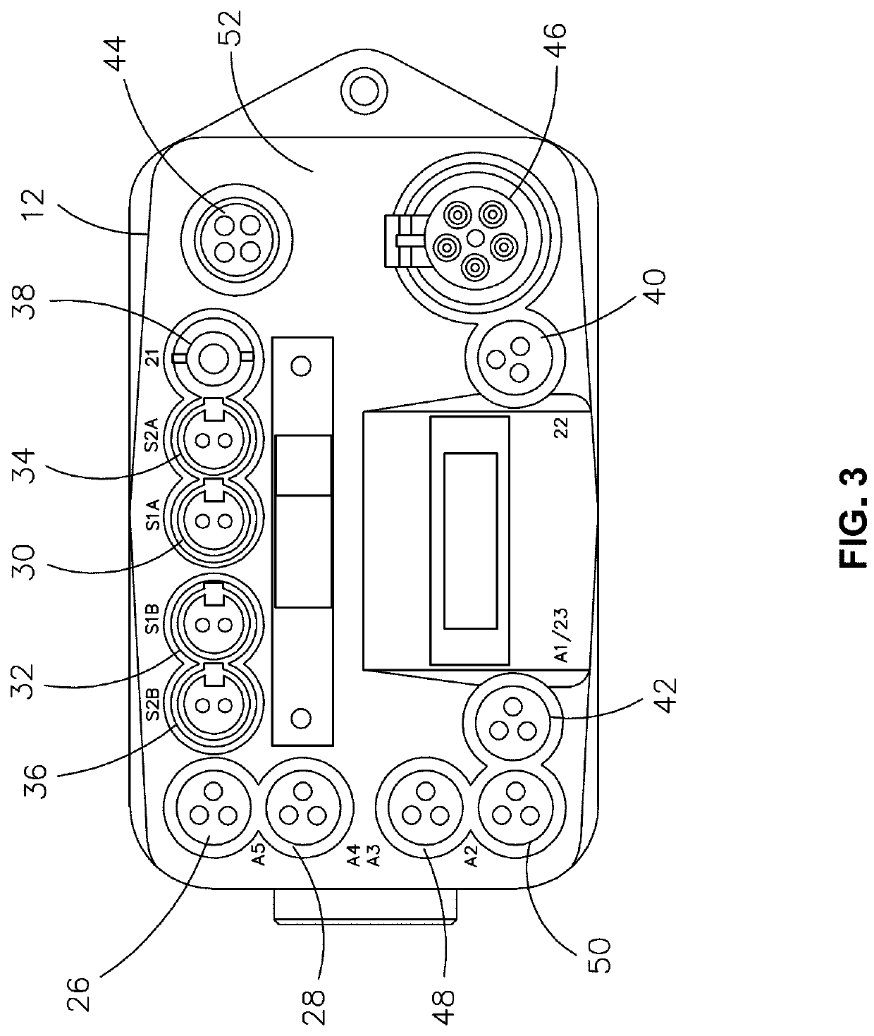
[0038]Referring to FIG. 6, the trailer control module 12 includes a processor 24 that is electrically coupled with, configured to receive data or instructions from, and configured to transmit data or instructions to: a brake supply pressure input 26, a brake control pressure input 28, a first wheel speed input 30, a second wheel speed input 32, a third wheel speed input 34, a fourth wheel speed input 36, a first valve output 38, a second valve output 40, a third valve output 42, a con...


PUM


Abstract

A method for monitoring a wheel system by comparing a wheel end temperature to a wheel end temperature threshold; generating a brake monitoring signal when at least one brake monitoring condition has occurred; and generating a wheel monitoring signal if a brake monitoring signal is generated when the wheel end temperature is greater than the wheel end temperature threshold. The brake monitoring conditions may include (i) a brake supply pressure is less than a brake supply pressure threshold; (ii) a brake control pressure is greater than a first brake control pressure threshold and a stop lamp power signal is not present; and / or (iii) the stop lamp power signal is present and the brake control pressure is not greater than a second brake control pressure threshold. A brake monitoring system configured to monitor a wheel system.

Description

CROSS-REFERENCE TO RELATED APPLICATIONS[0001]This application is based on and claims priority to U.S. Provisional Application Ser. No. 62 / 675,423, filed on May 23, 2018, which is incorporated herein by reference in its entirety.STATEMENT REGARDING FEDERALLY SPONSORED RESEARCH OR DEVELOPMENT[0002]Not applicable.STATEMENT REGARDING JOINT RESEARCH AGREEMENT[0003]Not applicable.BACKGROUND OF THE INVENTION1. Field of the Invention[0004]The present application relates generally to vehicle wheel system monitoring and, in particular, to a brake monitoring system and method with temperature monitoring.2. Description of Related Art[0005]Air operated braking systems have long been utilized to control commercial vehicles such as trucks and trailers, which typically have large gross vehicle weights, in a safe and effective manner. The considerable inertial mass of these heavy-duty vehicles, in combination with the high speeds at which they travel, requires a braking system which responds rapidly...

Claims


Application Information

Patent Timeline
Patent Type & Authority Patents(United States)
IPC IPC(8): B60T17/22B60C23/20
CPCB60T17/221B60C23/20B60T8/94B60T17/22F16D2066/001
Inventor ENGELBERT, DAVID G.GREENE, JAMESYURKONIS, CHARLESDELEON, MARCOS J.JENKINS, MICHAEL R.
Owner HALDEX BRAKE PROD CORP
Features
  • Generate Ideas
  • Intellectual Property
  • Life Sciences
  • Materials
  • Tech Scout
  • Unparalleled Data Quality
  • Higher Quality Content
  • 60% Fewer Hallucinations
Learn More