Display device
a display device and display technology, applied in the direction of identification means, electrical apparatus casings/cabinets/drawers, instruments, etc., can solve the problems of complicated overall structure and difficult to break the connection line, and achieve the effect of preventing overlap, reducing stress applied to the display, and being convenient to install
- Summary
- Abstract
- Description
- Claims
- Application Information
AI Technical Summary
Benefits of technology
Problems solved by technology
Method used
Image
Examples
first embodiment
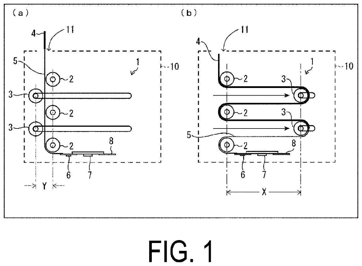
[0028]First, it is described below how the flexible display panel 1 (display area for display) is housed in the accommodation section 10 in a housing and pull-out type display device.
[0029](a) of FIG. 1 is an explanatory diagram illustrating a state in which the flexible display panel 1 is pulled out from the accommodation section 10 (the time of pull-out, that is, a case of displaying an image on the flexible display panel). (b) of FIG. 1 is an explanatory diagram illustrating a case in which the flexible display panel 1 is housed (the time of housing).
[0030]As illustrated in (a) and (b) of FIG. 1, the display device includes the flexible display panel 1 and the accommodation section 10. The display device includes a plurality of fixed guide members 2 formed of, for example, rollers and the like unable to move (fixed), and at least one movable guide member 3 formed of, for example, a roller and the like able to move. Note that FIG. 1 illustrates an example including two movable gui...
second embodiment
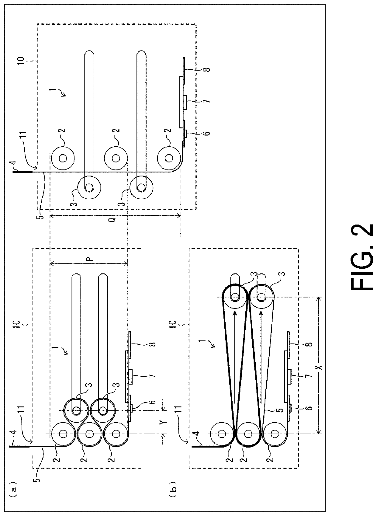
[0051]A second embodiment of the disclosure will be described below with reference to FIG. 2. Note that for the sake of convenience in description, members having the same functions as the members described in the first embodiment will be given the same reference signs, and descriptions thereof will be omitted.
[0052]In a housing and pull-out type display device of the second embodiment, a configuration to pull out a flexible display panel 1 is different from that of the first embodiment.
[0053]The configuration of the second embodiment differs from the configuration of the first embodiment in a point that fixed guide members 2 and movable guide members 3 are disposed in the positions and at the intervals illustrated in FIG. 2. This point will be described below.
[0054]That is, according to the configuration of the first embodiment, each of the plurality of movable guide members 3 passes through between the corresponding two fixed guide members 2 and moves in a predetermined direction ...
third embodiment
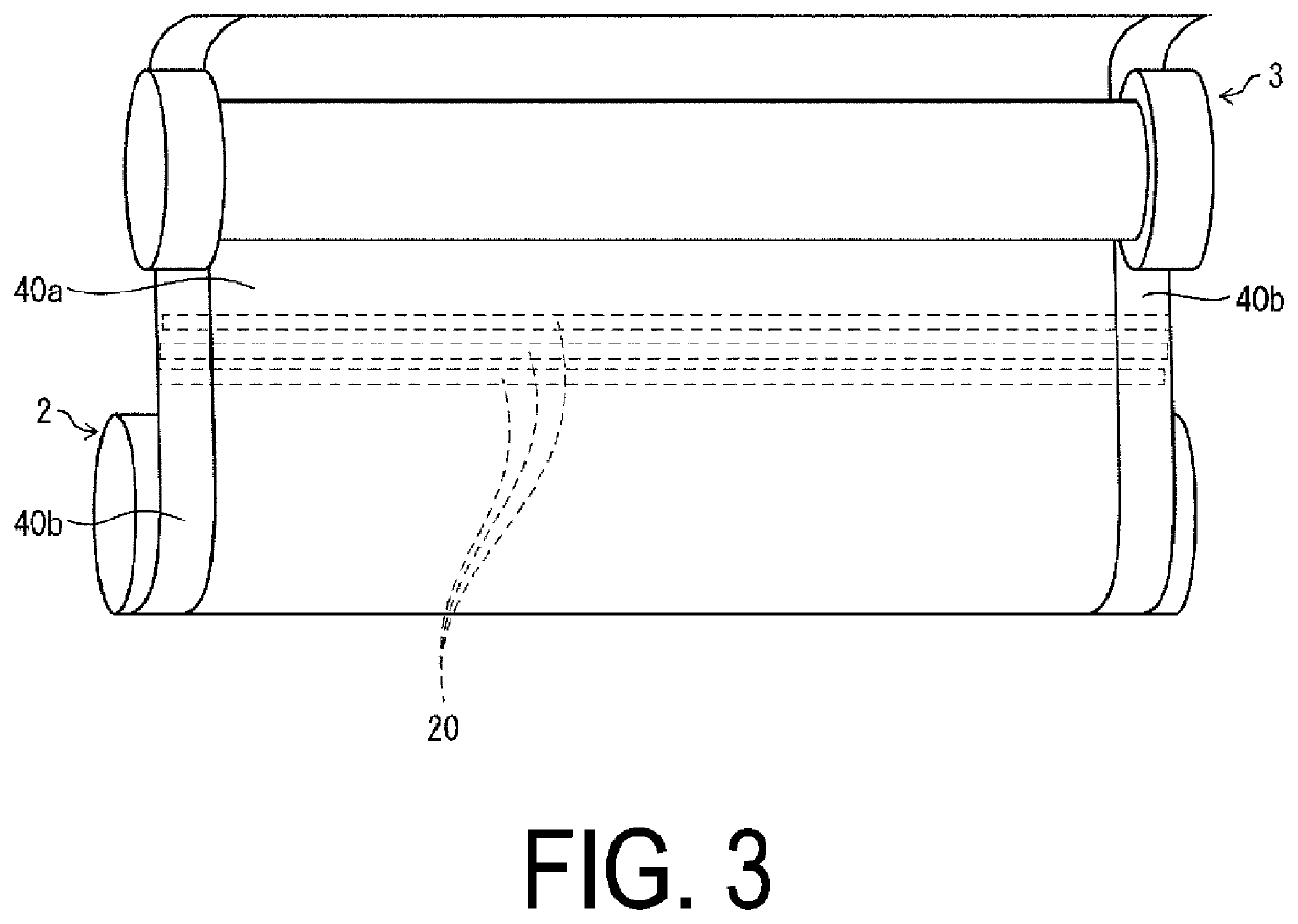
[0061]A third embodiment of the disclosure will be described below with reference to FIG. 3. For the sake of convenience in description, members having the same functions as the members described in the first and second embodiments will be given the same reference signs, and descriptions thereof will be omitted.
[0062]The fixed guide member 2 is configured to be disposed in such a manner as to make contact with a rear face of the flexible display panel 1. This contact does not cause the rear face of the flexible display panel 1 to experience stress, scratches, or the like.
[0063]On the other hand, in the movable guide member 3, a display surface of the flexible display panel 1 is disposed to be in contact with the fixed guide member 2. When disposed in this manner, the display surface of the flexible display panel 1 is damaged, and the display of the flexible display panel 1 is adversely affected.
[0064]To deal with this, the third embodiment further includes the following configuratio...
PUM
 Abstract
Description
Claims
Application Information
 - R&D
- Intellectual Property
- Life Sciences
- Materials
- Tech Scout
- Unparalleled Data Quality
- Higher Quality Content
- 60% Fewer Hallucinations
Browse by: Latest US Patents, China's latest patents, Technical Efficacy Thesaurus, Application Domain, Technology Topic, Popular Technical Reports.
© 2025 PatSnap. All rights reserved.Legal|Privacy policy|Modern Slavery Act Transparency Statement|Sitemap|About US| Contact US: help@patsnap.com


