Laser machining system for machining a workpiece by means of a laser beam and method for controlling a laser machining system

a laser beam and machining system technology, applied in the direction of laser beam welding apparatus, instruments, measurement devices, etc., can solve the problems of difficult to prevent drift, the method for determining the deepest point of the vapor capillary is significantly more complex, and the measurement position is not ideal during the welding process

Active Publication Date: 2022-07-26
PRECITEC GMBH
View PDF16 Cites 5 Cited by
  • Summary
  • Abstract
  • Description
  • Claims
  • Application Information

AI Technical Summary

Benefits of technology

[0025]Thereby, the position of the optical measuring beam and the position of the vapor capillary may be determined and adjusted for an accurate and continuous measurement of the depth of the vapor capillary, e.g. by interferometric distance measurement, during a machining process, preferably in real time. The position of the measuring spot may then be adjusted based on an ideal position relative to the position of the vapor capillary for measuring the maximum depth of the vapor capillary. An interruption of the measurement of the welding depth or the depth of the vapor capillary by the optical measuring device or of the control of the measuring position is therefore not necessary. The point of incidence of the optical measuring beam on the workpiece and its alignment with a suitable position for measuring the depth of the vapor capillary may thus be carried out reliably, inexpensively and simply.
[0044]Preferably, a wavelength of the visualization beam is smaller than a wavelength of the measuring beam. Losses in the light power of the visualization beam when coupling it into the optical fiber of the optical measuring device may thereby be avoided. A monomode fiber for the wavelength of the measuring beam may therefore be used.

Problems solved by technology

However, a change in the position of the measuring beam, e.g. due to drift of deflection units or other inaccuracies in the laser machining system, is not excluded and leads to a deviation from the ideal measuring position during the welding process.
When using galvoscanners as a deflection unit for the measuring beam, it is difficult to prevent drift.
In the case of a curved weld seam, the method for determining the deepest point of the vapor capillary is therefore significantly more complex, since each segment of the curved weld seam has a different optimal position of the measuring spot to be determined or set in advance for each segment.
As a result, reliable information about the welding depth cannot be collected during this time.
Such a model is very complex due to the large number of different welding parameters.
In addition, such a procedure requires a lot of effort to establish and evaluate the model based on experiments.
Furthermore, this approach does not solve the problem that, e.g. in the event of a drift of the deflection unit or inaccuracies, an incorrect position of the measuring beam is not recognized.
However, this alternative is uneconomical due to high costs.
This reduces the measuring range available for the welding depth measurement.
Furthermore, with these alternatives there is also the problem that, in the event of a drift, the position of the measuring beam measuring the depth of the vapor capillary is no longer exactly known.

Method used


Image

  • Laser machining system for machining a workpiece by means of a laser beam and method for controlling a laser machining system
  • Laser machining system for machining a workpiece by means of a laser beam and method for controlling a laser machining system
  • Laser machining system for machining a workpiece by means of a laser beam and method for controlling a laser machining system

Examples


first embodiment

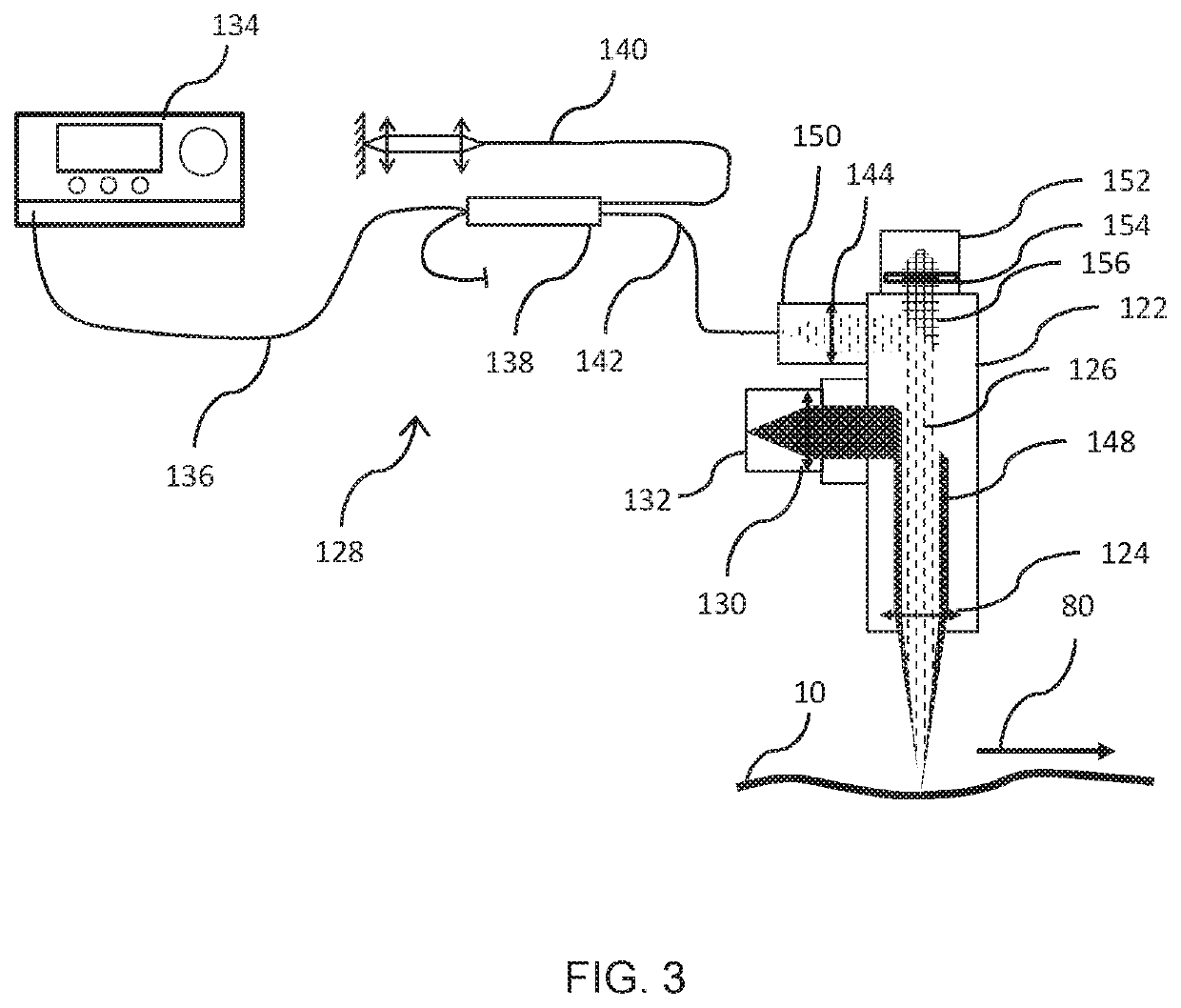
[0056]FIG. 3 is a schematic view of a laser machining system 100 according to the present invention. The laser machining system 100 comprises a machining head 122, for example a laser welding head or a laser cutting head.

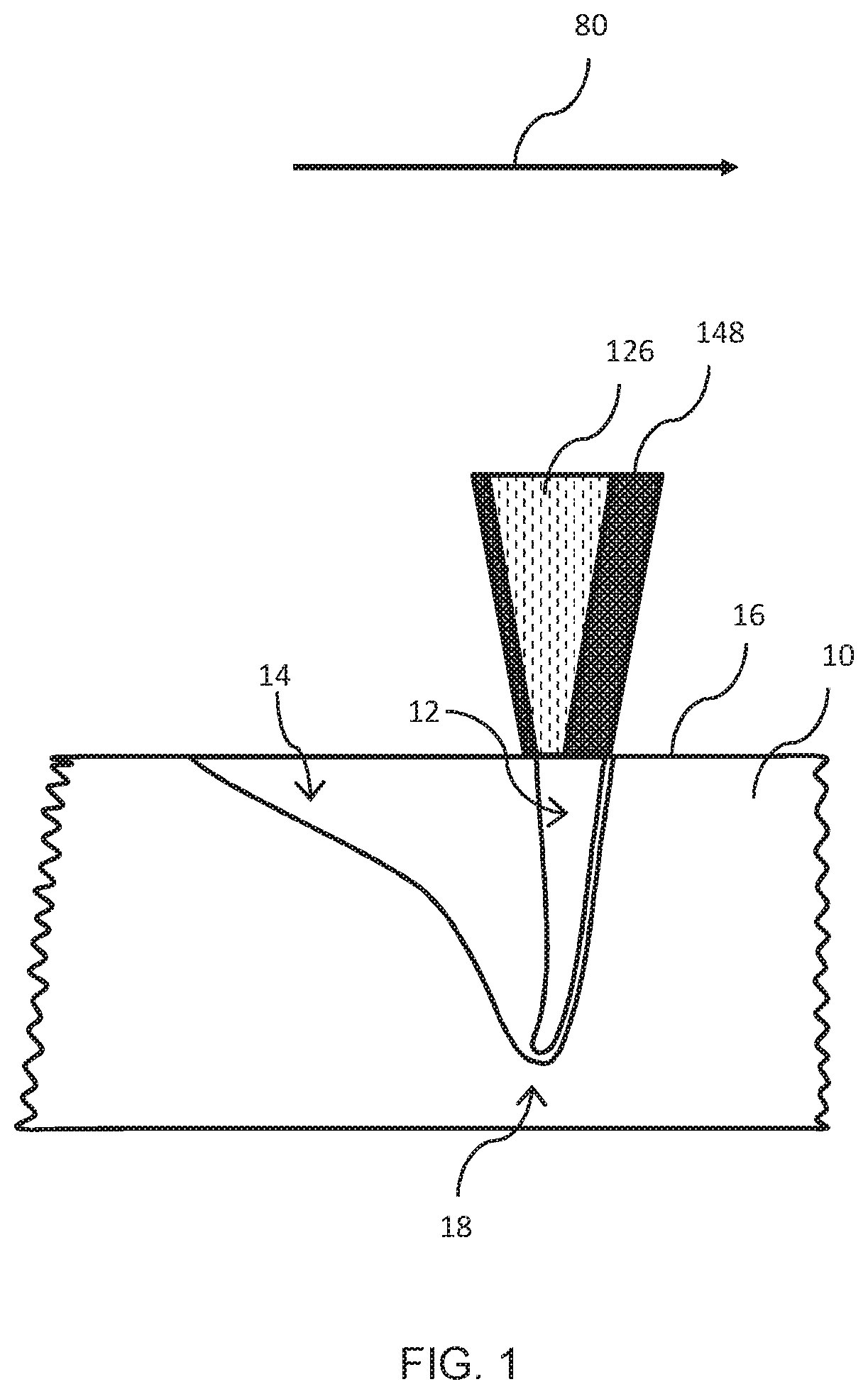
[0057]The laser machining system 100 further comprises a laser device (not shown) for providing a laser beam 148 (also referred to as a “machining beam” or “machining laser beam”) and an optical measuring device 128 configured for interferometric distance measurement by means of an optical measuring beam 126. For example, a distance between a workpiece 10 to be machined and an end portion of the machining head 122, such as a nozzle or a cross jet, is measured. The end portion, such as the nozzle or cross jet, has an opening through which the laser beam 148 exits from the machining head 122, optionally along with a process gas.

[0058]The laser machining system 100 or parts thereof, for example the machining head 122, may be movable along at least one machining directi...

second embodiment

[0087]FIG. 6 shows a laser machining system 300 according to the invention.

[0088]The laser machining system 300 corresponds to the laser machining system 100 described above with reference to FIG. 3, but has a visualization unit 370 for visualizing the optical measuring beam 126 or the measuring spot 18. The visualization unit 370 may include a light source 372 configured to generate a visualization beam (also called “visualization light beam”). Due to the limited light output of light sources for the optical measuring beam 126, for example conventional SLDs, the visualization unit 370 may be provided with the light source 372 in order to make the position of the optical measuring beam 126 visible in the image.

[0089]Light from the visualization unit 370 is preferably coupled into the beam path of the optical measuring beam 126. The coupling is preferably carried out by means of a beam splitter, for example the fiber coupler 138, configured to couple the visualization beam into the o...


PUM

PropertyMeasurementUnit
wavelength rangeaaaaaaaaaa
wavelengthaaaaaaaaaa

Abstract

A laser machining system, or laser welding system, for machining a workpiece includes: a laser machining head for directing a laser beam onto a workpiece to produce a vapor capillary; an optical measuring device using an optical measuring beam; an image acquisition unit to capture an image of a region of the workpiece surface containing the vapor capillary and a measuring spot produced by irradiation with the measuring beam. The system determines positions of the measuring spot and vapor capillary based on the image. A method includes: directing the laser beam onto a workpiece surface to produce a vapor capillary; directing an optical measuring beam onto the surface to measure a depth of the vapor capillary; capturing an image of a region containing the vapor capillary and a measuring spot from the optical measuring beam; and determining, based on the captured image, position of the measuring spot and vapor capillary.

Description

CROSS-REFERENCE TO RELATED APPLICATION[0001]This application claims priority from German Application No. 10 2019 103 734.4 filed Feb. 14, 2019, the entire content of which is incorporated herein by reference.FIELD OF THE INVENTION[0002]The present invention relates to a laser machining system for machining a workpiece by means of a laser beam, in particular a laser welding system, and a method for controlling a laser machining system. The present invention preferably relates to a laser machining system with an optical coherence tomograph for interferometric distance measurement, and to a method for controlling the same.BACKGROUND OF THE INVENTION[0003]In a machining system for machining a workpiece by means of a laser beam, the laser beam exiting from a laser light source or an end of an optical fiber is focused or collimated onto the workpiece to be machined with the aid of a beam guiding and focusing optics. The machining may comprise, for example, laser cutting, laser soldering o...

Claims


Application Information

Patent Timeline
Patent Type & Authority Patents(United States)
IPC IPC(8): B23K26/04B23K26/03B23K26/21B23K26/70G01B9/02091
CPCB23K26/032B23K26/21B23K26/702G01B9/02091B01D1/0017G01B9/0203G01B11/22B23K31/125
Inventor MOSER, RÜDIGER
Owner PRECITEC GMBH
Why Eureka
Try Eureka