Laser machining system for machining a workpiece by means of a laser beam and method for controlling a laser machining system
a laser beam and machining system technology, applied in the direction of manufacturing tools, separation processes, instruments, etc., can solve the problems of difficult to prevent drift, the method for determining the deepest point of the vapor capillary is significantly more complex, and the measurement position is not ideal during the welding process
- Summary
- Abstract
- Description
- Claims
- Application Information
AI Technical Summary
Benefits of technology
Problems solved by technology
Method used
Image
Examples
first embodiment
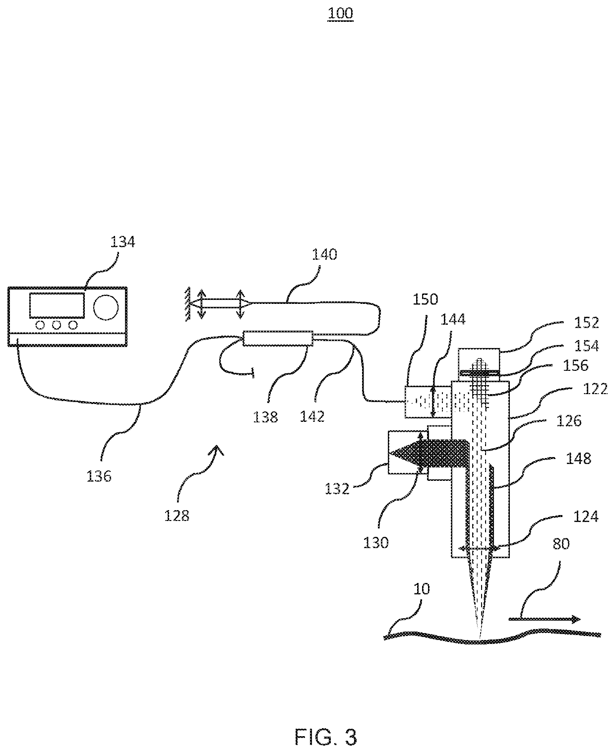
[0056]FIG. 3 is a schematic view of a laser machining system 100 according to the present invention. The laser machining system 100 comprises a machining head 122, for example a laser welding head or a laser cutting head.
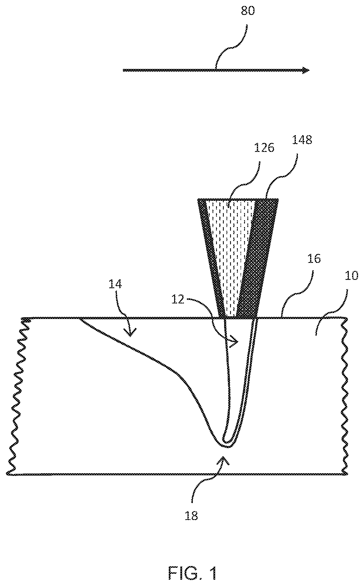
[0057]The laser machining system 100 further comprises a laser device (not shown) for providing a laser beam 148 (also referred to as a “machining beam” or “machining laser beam”) and an optical measuring device 128 configured for interferometric distance measurement by means of an optical measuring beam 126. For example, a distance between a workpiece 10 to be machined and an end portion of the machining head 122, such as a nozzle or a cross jet, is measured. The end portion, such as the nozzle or cross jet, has an opening through which the laser beam 148 exits from the machining head 122, optionally along with a process gas.
[0058]The laser machining system 100 or parts thereof, for example the machining head 122, may be movable along at least one machining directi...
second embodiment
[0087]FIG. 6 shows a laser machining system 300 according to the invention.
[0088]The laser machining system 300 corresponds to the laser machining system 100 described above with reference to FIG. 3, but has a visualization unit 370 for visualizing the optical measuring beam 126 or the measuring spot 18. The visualization unit 370 may include a light source 372 configured to generate a visualization beam (also called “visualization light beam”). Due to the limited light output of light sources for the optical measuring beam 126, for example conventional SLDs, the visualization unit 370 may be provided with the light source 372 in order to make the position of the optical measuring beam 126 visible in the image.
[0089]Light from the visualization unit 370 is preferably coupled into the beam path of the optical measuring beam 126. The coupling is preferably carried out by means of a beam splitter, for example the fiber coupler 138, configured to couple the visualization beam into the o...
PUM
| Property | Measurement | Unit |
|---|---|---|
| wavelength range | aaaaa | aaaaa |
| wavelength range | aaaaa | aaaaa |
| wavelength | aaaaa | aaaaa |
Abstract
Description
Claims
Application Information
 - R&D
- Intellectual Property
- Life Sciences
- Materials
- Tech Scout
- Unparalleled Data Quality
- Higher Quality Content
- 60% Fewer Hallucinations
Browse by: Latest US Patents, China's latest patents, Technical Efficacy Thesaurus, Application Domain, Technology Topic, Popular Technical Reports.
© 2025 PatSnap. All rights reserved.Legal|Privacy policy|Modern Slavery Act Transparency Statement|Sitemap|About US| Contact US: help@patsnap.com


