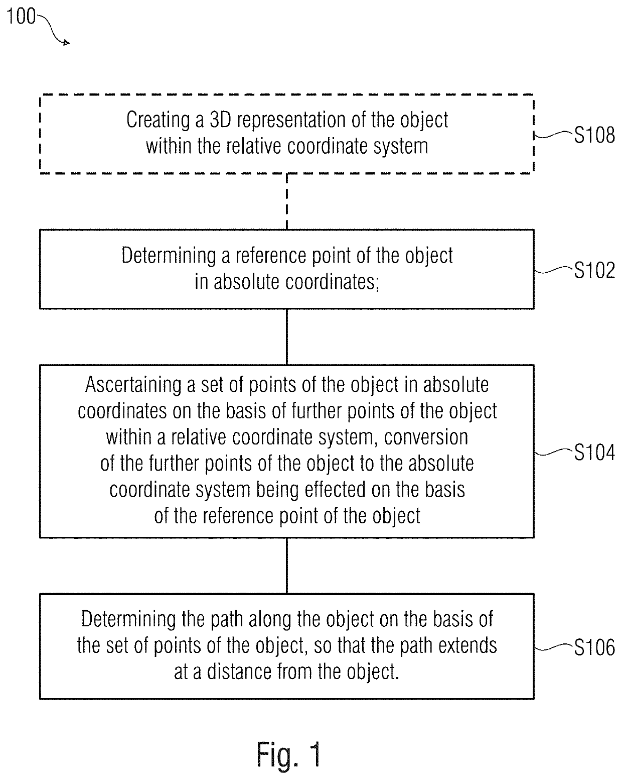
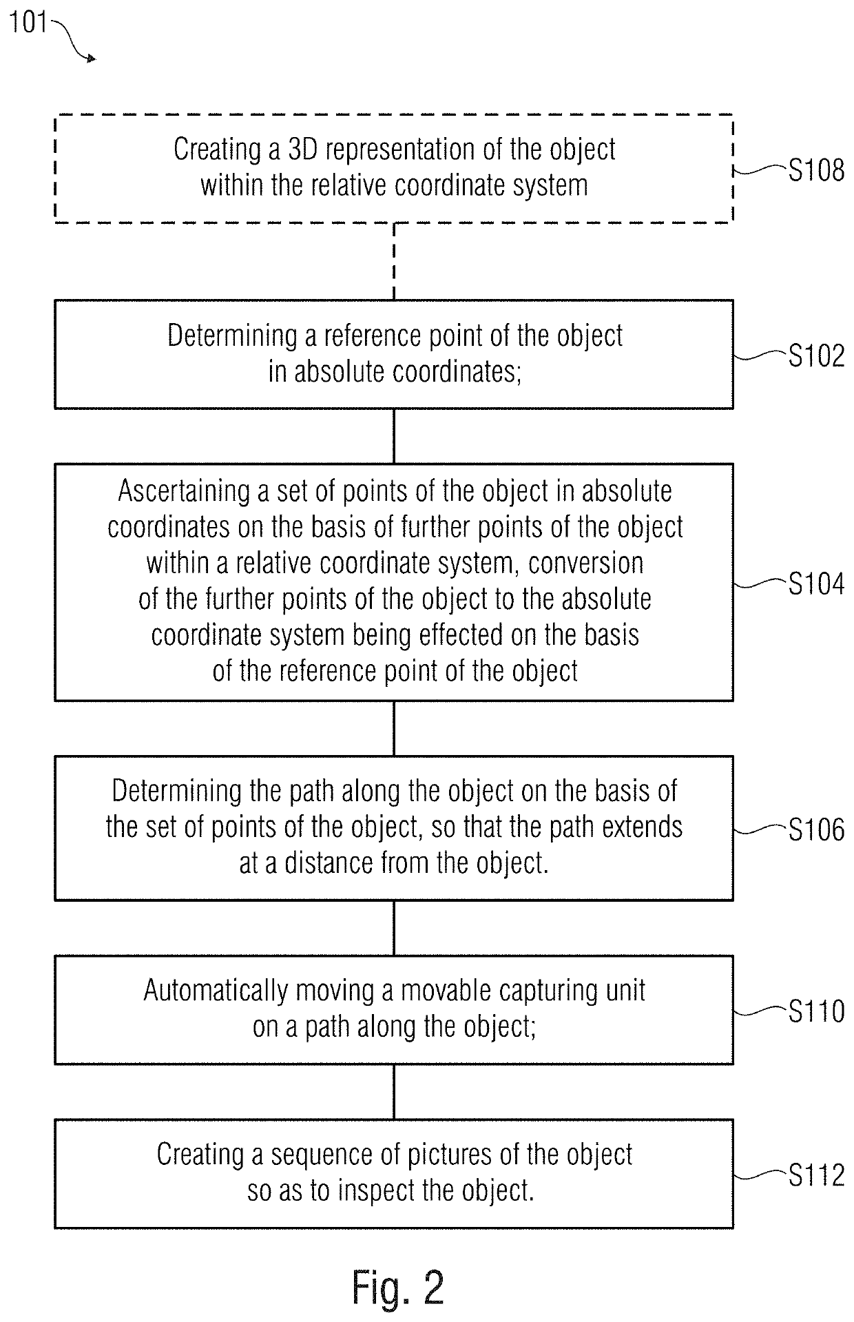
[0009]The present invention is based on the idea of automating inspection of objects. To this end, it is initially important that a route along an object be determined along which the object may be inspected. Here it is important at first to determine the exact position of the object. Frequently, however, dimensioning is known only from, e.g., dimensional drawings or (3D) computer models of the object, whereas absolute coordinates of, e.g. a geographic coordinate system, of the object are not known. Said coordinates will also be referred to as relative coordinates below. In order to obtain the absolute coordinates, it will suffice, however, to determine only one point of the object in absolute terms and to transform the further points in relative coordinates to absolute coordinates on the basis of the reference point. Thus, expensive position finding of a multitude of reference points may be avoided. The absolute coordinates may then be used for finding the position of the path, so that also the (corner) points of the path (or polygon) are available in absolute coordinates.
[0013]In accordance with embodiments, reproducing said movements in the model provides the possibility of adapting the trajectory along the object to the changing conditions in real time. In accordance with embodiments, a movement of the unit, e.g., of the drone, along the moving object or along the moving part of the object is made possible.
[0014]Determining of the coordinates in relation to the object may be effected by determining the path by means of a distance that is to be kept from the object. Here, the distance from the object may be ascertained in a direction perpendicular to polygon surfaces located between the set of points of the object. Said method enables optimum positioning of the path to the object to be captured so as to perform, e.g., picture-taking or measurements along the path of, or on, the object. In addition or alternatively, the path may also be determined such that at least 40%, at least 60% or at least 80% of the total length of the path extends in parallel with polygon surfaces located between the set of points of the object. Polygon surfaces may connect adjacent points / vertices so as to span the surface of the object and to create a model of the object.
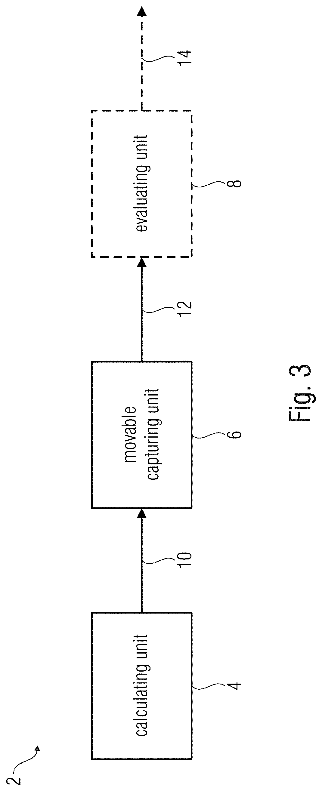
[0020]Embodiments further show the calculating unit which is configured to define, along the path, trigger locations for the movable capturing unit as a function of a visual field of the movable capturing unit. The visual field of the movable capturing unit may be influenced and / or set, e.g., by the focal length and / or resolution of an objective of the capturing unit. In other words, the visual field may be a section of the environment which may be captured by the movable capturing unit. The movable capturing unit is configured to take (or capture) a picture at the trigger locations. This is advantageous since consequently, the number of pictures that may be used is specified in advance, for example on the basis of the objective used and / or of the distance of the path (i.e., of the movable capturing unit) from the object. Said specification may advantageously be performed in local terms, so that the capturing unit will trigger (release the shutter) upon reaching a trigger location rather than at random within specific time intervals. Thus, the number of images (or pictures) may be reduced to a minimum. This may amount to less than 100 pictures, less than 60 pictures or less than 40 pictures for a blade / vane of a wind turbine in order to inspect same from both sides. This reduces the expenditure in terms of evaluating the pictures as compared to uncontrolled triggering, or triggering based on mere time intervals (or even a video).
[0022]In accordance with embodiments, the movable capturing unit is configured to set a capturing direction to a point among the set of points. In other words, the movable capturing means aligns a camera such that the latter is aligned to a predetermined point of the object and will take a picture in said direction, irrespective of a current (absolute or spatial) position of the movable capturing means. In yet other words, the heading of the capturing means is aligned to the predetermined point of the object. This ensures that the movable capturing unit will capture the desired image section rather than being turned away from the object, for example. In addition, in this manner, even relatively large deviations of the capturing unit from a predetermined trigger location may be tolerated since successive images will overlap (approximately by a set value) and since, therefore, pictures will be obtained from all locations of the objects without omitting a surface area that should be captured. Potentially occurring aberrations (which are due to the fact that the object is not captured at right angles, but in an oblique manner, i.e., at an angle deviating from the right angle) may be compensated for. However, if a surface area of the object is not captured, the movable capturing unit may once again fly to said location so as not to have to do without information about this surface area.


