Battery module, method for the production thereof, and battery

Active Publication Date: 2022-07-26
ROBERT BOSCH GMBH
View PDF19 Cites 0 Cited by
  • Summary
  • Abstract
  • Description
  • Claims
  • Application Information

AI Technical Summary

Benefits of technology

[0009]The battery module and the method for the production thereof according to the invention have the advantage that reliable mechanical fixing of a multiplicity of battery cells in the battery module, and an efficient dissipation of heat from the battery module, are possible. Here, in particular, it is possible for the formation of air-filled cavities owing to production-induced tolerances between the battery cells and a cooling element of the battery module to be reduced or even prevented entirely. In this way, the heat transfer between the battery cells and the cooling element is advantageously increased, and an amount of heat that can be dissipated from the battery module is thus also increased overall. It is also thereby advantageous that reliable mechanical fixing of the battery cells in a battery module housing of the battery module is possible in particular by means of the cooling element, such that additional measures for fixing can be omitted.

Problems solved by technology

Ageing processes owing to charging and discharging processes in the individual battery cells give rise to internal forces, which have the effect that the individual battery cells do not remain constant in terms of shape over the service life, it rather being the case that these processes, referred to as swelling, deform the housing of the battery cells.

Method used


Image

  • Battery module, method for the production thereof, and battery
  • Battery module, method for the production thereof, and battery
  • Battery module, method for the production thereof, and battery

Examples


first embodiment

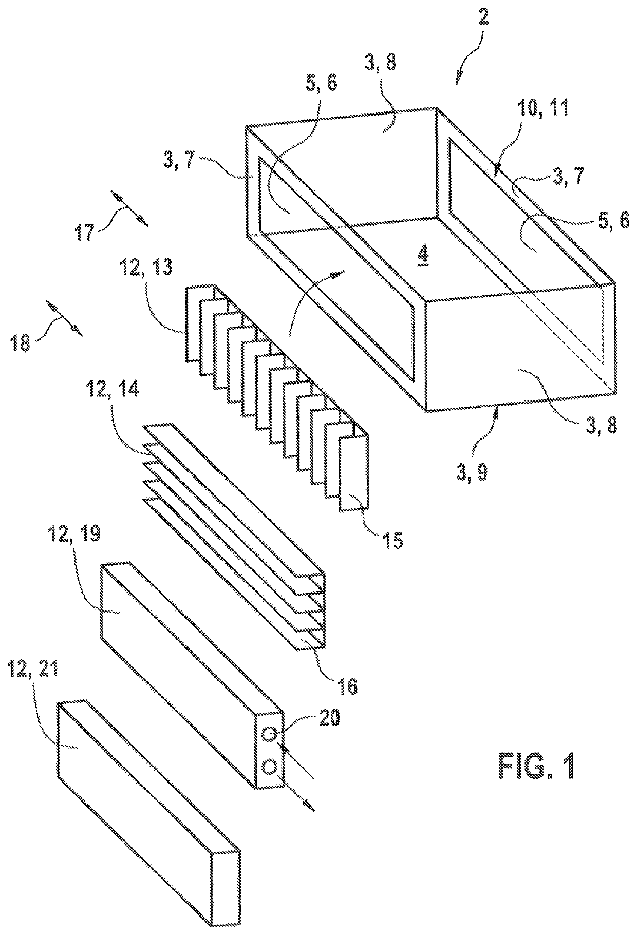
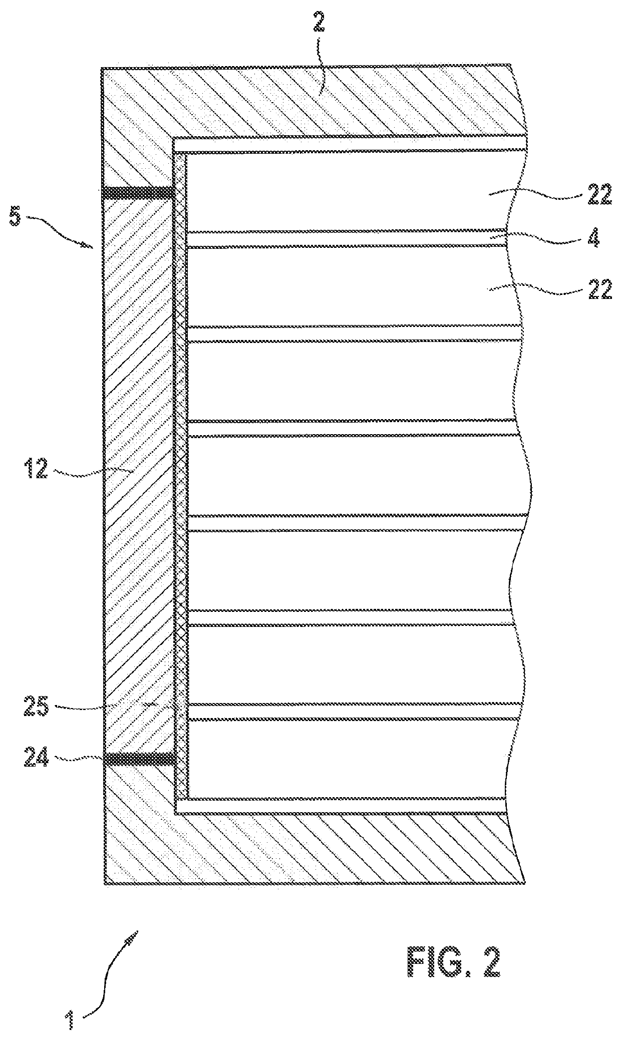
[0054]The battery module housing 2 furthermore has a cooling element receptacle 5. In particular, the battery module housing 2 shown in FIG. 1 has two cooling element receptacles 5. In the invention shown in FIG. 1, the cooling element receptacle 5 is formed as an opening 6 running through one of the housing walls 3. In particular, the cooling element receptacle 5 may in this case preferably be arranged on a side surface 7 of the battery module housing 2 in order to form as large as possible a contact area between the battery cells 22 and a cooling element 12. Furthermore, the cooling element receptacle 5 may self-evidently also be formed on a face surface 8 of the battery module housing 2, or formed on a base surface 9 of the battery module housing 2.

[0055]The battery module housing 2 preferably has, on a top side 10, an opening 11 through which the battery cells 22 (not shown in FIG. 1) can be inserted into the battery module housing 2. It is furthermore preferable for the opening...

second embodiment

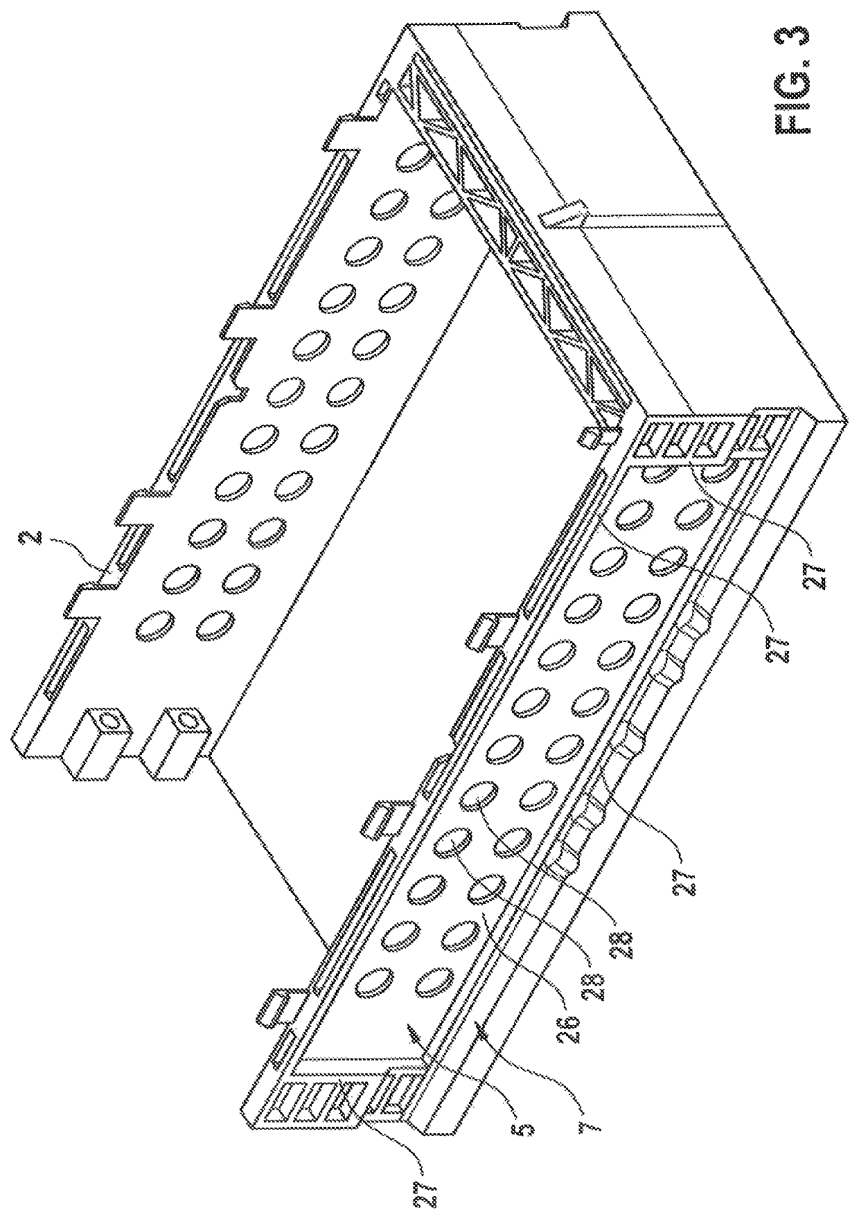
[0071]FIG. 3 schematically shows, in a perspective view, a battery module housing 2 according to the invention, which differs from the battery module housings 2 shown in FIGS. 1 and 2 in particular by the form of the cooling element receptacle 5.

[0072]Here, a housing wall 26 arranged directly adjacent to the cooling element receptacle 5 has a smaller wall thickness than the housing walls 27 surrounding the cooling element receptacle 5. At this juncture, it is pointed out that the housing wall 26 arranged directly adjacent to the cooling element receptacle 5 is intended to refer to that housing wall which, after the arrangement of the cooling element 12, is arranged directly adjacent to one of the relatively large side surfaces of the cooling element 12 and is in particular also arranged directly between the cooling element 12 and the battery cells 22.

[0073]Furthermore, FIG. 3 shows that the housing wall 26 arranged directly adjacent to the cooling element receptacle 5 of the battery...


PUM

PropertyMeasurementUnit
diameteraaaaaaaaaa
diameteraaaaaaaaaa
diameteraaaaaaaaaa

Abstract

A battery module having a battery module housing (2) which has a multiplicity of housing walls (3) which form an interior space (4), wherein a multiplicity of battery cells (22) is arranged in the interior space (4), and the battery module housing (2) furthermore has a cooling element receptacle (5), wherein a cooling element (12) of the battery module (1) is arranged in the cooling element receptacle (5) of the battery module housing (2).

Description

BACKGROUND OF THE INVENTION[0001]The invention relates to a battery module and to a method for the production thereof. The present invention also relates to a battery having a battery module of said type.[0002]From the prior art, it is known that batteries, in particular lithium-ion batteries, are composed of at least one battery module or advantageously of a multiplicity of battery modules. Furthermore, a battery module also preferably has a multiplicity of individual battery cells, which are interconnected with one another to form the battery module. Here, the individual battery cells may be connected in series or in parallel with one another.[0003]Ageing processes owing to charging and discharging processes in the individual battery cells give rise to internal forces, which have the effect that the individual battery cells do not remain constant in terms of shape over the service life, it rather being the case that these processes, referred to as swelling, deform the housing of t...

Claims


Application Information

Patent Timeline
Patent Type & Authority Patents(United States)
IPC IPC(8): H01M10/613H01M10/653H01M10/6551H01M10/6556H01M10/659H01M10/04H01M50/20H01M50/24H01M10/0525H01M50/209H01M50/227H01M50/264
CPCH01M10/613H01M10/0481H01M10/653H01M10/659H01M10/6551H01M10/6556H01M50/20H01M50/24H01M10/0525H01M10/647H01M10/6554H01M50/227H01M50/209H01M50/264
Inventor BEHM, HENRIK WOLFGANGLORENZ, LISATEMIZ, SINASIBAUMANN, STEFAN
Owner ROBERT BOSCH GMBH
Why Eureka
Try Eureka