
Method for controlling a fuel delivery system

a fuel delivery system and fuel injection technology, applied in the direction of electric control, fuel injection control, machines/engines, etc., can solve the problem of increasing the pressure in the fuel delivery system, and achieve the effect of improving the control of the fuel delivery system and broadening the operating rang

Active Publication Date: 2019-03-19
VITESCO TECH GERMANY GMBH
View PDF9 Cites 0 Cited by
  • Summary
  • Abstract
  • Description
  • Claims
  • Application Information

AI Technical Summary

Benefits of technology

The present invention provides a method to control the fuel delivery system in an improved way, without using a pressure sensor. The method can be applied to different fuel delivery systems and can compensate for pressure loss by increasing the pump rotational speed. The fuel delivery quantity is determined based on the fuel requirement of the internal combustion engine and the fuel quantity required for the operation of suction jet pumps, which is considerably lower than the fuel requirement of the engine. The method uses a characteristic diagram that is specific for each fuel delivery system, which can be determined based on tests or calculations. The method provides a very accurate determination of the pressure in the fuel delivery system.

Problems solved by technology

As a result, the pressure in the fuel delivery system rises somewhat, since an additional pressure loss is produced by way of the suction jet pump and other possibly present consumers.

Method used


Image

  • Method for controlling a fuel delivery system
  • Method for controlling a fuel delivery system

Examples


Embodiment Construction

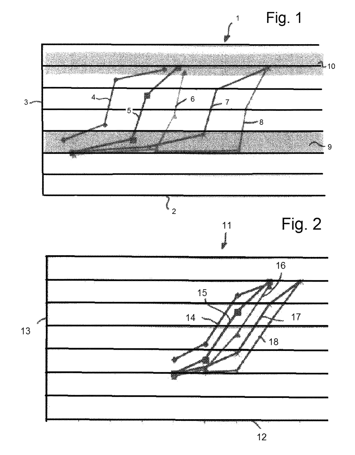
[0033]FIG. 1 shows a graph 1. In the graph 1, the fuel delivery quantity of a fuel delivery pump in a fuel delivery system is plotted on the X-axis 2. Here, the fuel delivery quantity is plotted for a range from zero liters per hour at the point of intersection with the Y-axis 3 up to 80 liters per hour on the right-hand end region of the X-axis 2. The pressure that prevails in the fuel delivery system is plotted on the Y-axis 3. The curves 4, 5, 6, 7, and 8 represent the respective fuel requirement of an internal combustion engine. The curve 4 corresponds to a fuel requirement of 20 liters per hour, the curve 5 corresponds to a fuel requirement of 30 liters per hour, the curve 6 corresponds to a fuel requirement of 40 liters per hour, the curve 7 corresponds to a fuel requirement of 50 liters per hour, and the curve 8 corresponds to a fuel requirement of 60 liters per hour. The fuel requirements of the graph 1 are by way of example and represent values for a specific fuel delivery ...


PUM


Abstract

A method for controlling a fuel delivery system of an internal combustion engine, having a fuel delivery pump that is driven by an electric motor. The pressure that prevails in the fuel delivery system is determined by a volume difference between the fuel quantity delivered by the fuel delivery pump and the fuel requirement of the internal combustion engine and / or of the fuel delivery system.

Description

CROSS REFERENCE TO RELATED APPLICATIONS[0001]This is a U.S. national stage of application No. PCT / EP2016 / 059159, filed on Apr. 25, 2016. Priority is claimed on German Application No. DE102015207700.4, filed Apr. 27, 2015, the content of which is incorporated here by reference.BACKGROUND OF THE INVENTION1. Field of the Invention[0002]The invention relates to a method for controlling a fuel delivery system of an internal combustion engine, having a fuel delivery pump driven by electric motor.2. Description of the Prior Art[0003]Fuel delivery pumps are used in fuel delivery systems of motor vehicles to meet the fuel requirement of the internal combustion engine. In addition, the operation of additional assemblies, such as suction jet pumps, is made possible by the fuel delivered by way of the fuel delivery pump.[0004]In order to make a precise control of the fuel delivery pump possible, the pressure in the fuel delivery system is required as a relevant variable. The determination of th...

Claims


Application Information

Patent Timeline
Patent Type & Authority Patents(United States)
IPC IPC(8): F02D1/02F02D41/38F02D41/30F02D41/24
CPCF02D1/02F02D41/3836F02D41/3854F02D2200/0614F02D41/3082F02D2200/0602F02D2200/0604F02D41/2432
Inventor BEHRENDT, GERALD
Owner VITESCO TECH GERMANY GMBH
Learn More