Medical imaging facility and a measurement method for detecting a position of a transport device of the medical imaging facility

a technology of medical imaging and measurement method, which is applied in the direction of diagnostics, distance measurement, instruments, etc., can solve the problem of enabling additional costs for a specific equipping of the transmit element, and achieve the effect of/or multiplicity of the detected position, and advantageously increasing the accuracy dependent on the measurement method

Inactive Publication Date: 2013-04-09
SIEMENS HEALTHCARE GMBH
View PDF9 Cites 0 Cited by
  • Summary
  • Abstract
  • Description
  • Claims
  • Application Information

AI Technical Summary

Benefits of technology

[0010]It is proposed that the position detection device has at least one reflector element. The medical imaging facility is especially formed by a magnetic resonance tomography device, a computed tomography device and / or a PET device and has a imaging area in which an imaging examination of an object under examination, especially a patient, can be undertaken. A reflector element is intended to be understood in this context in particular as an element by means of which incident radiation, especially the position measurement radiation, can be reflected, with the reflection especially occurring explicitly in a pre-determined direction, especially on the detector element or further reflector elements. Preferably the reflector element is arranged along a radiation path of the position measurement radiation between the at least one transmit element and the at least one detector element. The inventive design enables an advantageous multiplicity of a distance from the transmit element to the transport device, especially to a reference point of the transport device as a result of at least one and especially advantageously of a multiple reflection of the position measurement radiation at the at least one reflector element along a path from the transmit element to the detector element. In this manner a precise detection of the position of the transport device can be achieved, in that an inaccuracy in a measurement method can be significantly reduced by the multiplication of the distance.
[0024]If the position measurement beam is reflected after its transmission by the at least one transmit element, first of all at the first reflector element and subsequently at the at least one further reflector element, an advantageous multiplicity of a distance between the at least one transmit element and the transport device, especially to a reference marking of the transport device, is achieved. As well as this, with a movement and / or displacement of the transport device by a distance dx, a duplication of the change in distance dx can be achieved during a detection of the position of the transport device and thereby an accuracy dependent on a measurement method can advantageously be increased. A factor of the multiplicity and / or of the duplication is preferably dependent on a number of the reflector elements which are arranged within the beam path of the position measurement team and / or on a size of individual reflector elements so that a number of reflections can take place at one reflector element along the beam path. Especially advantageously the position the measurement beam is reflected once again at the first reflector element after a reflection at the at least one further reflector element.

Problems solved by technology

This enables additional costs for a specific equipping of the transmit element and / or of the detector element to be saved.

Method used


Image

  • Medical imaging facility and a measurement method for detecting a position of a transport device of the medical imaging facility
  • Medical imaging facility and a measurement method for detecting a position of a transport device of the medical imaging facility
  • Medical imaging facility and a measurement method for detecting a position of a transport device of the medical imaging facility

Examples


Embodiment Construction

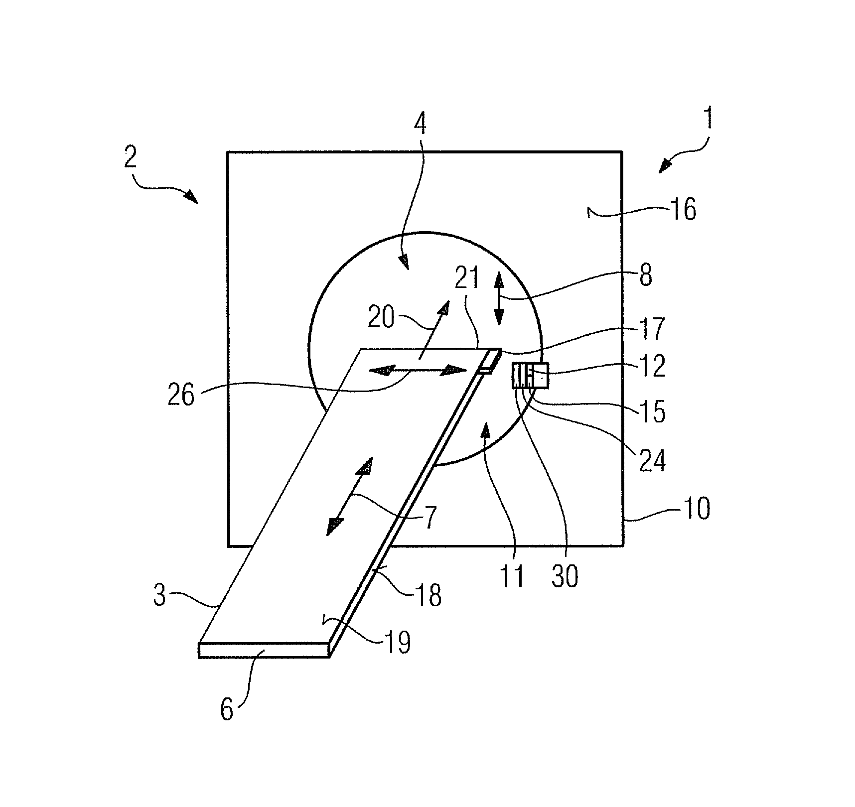
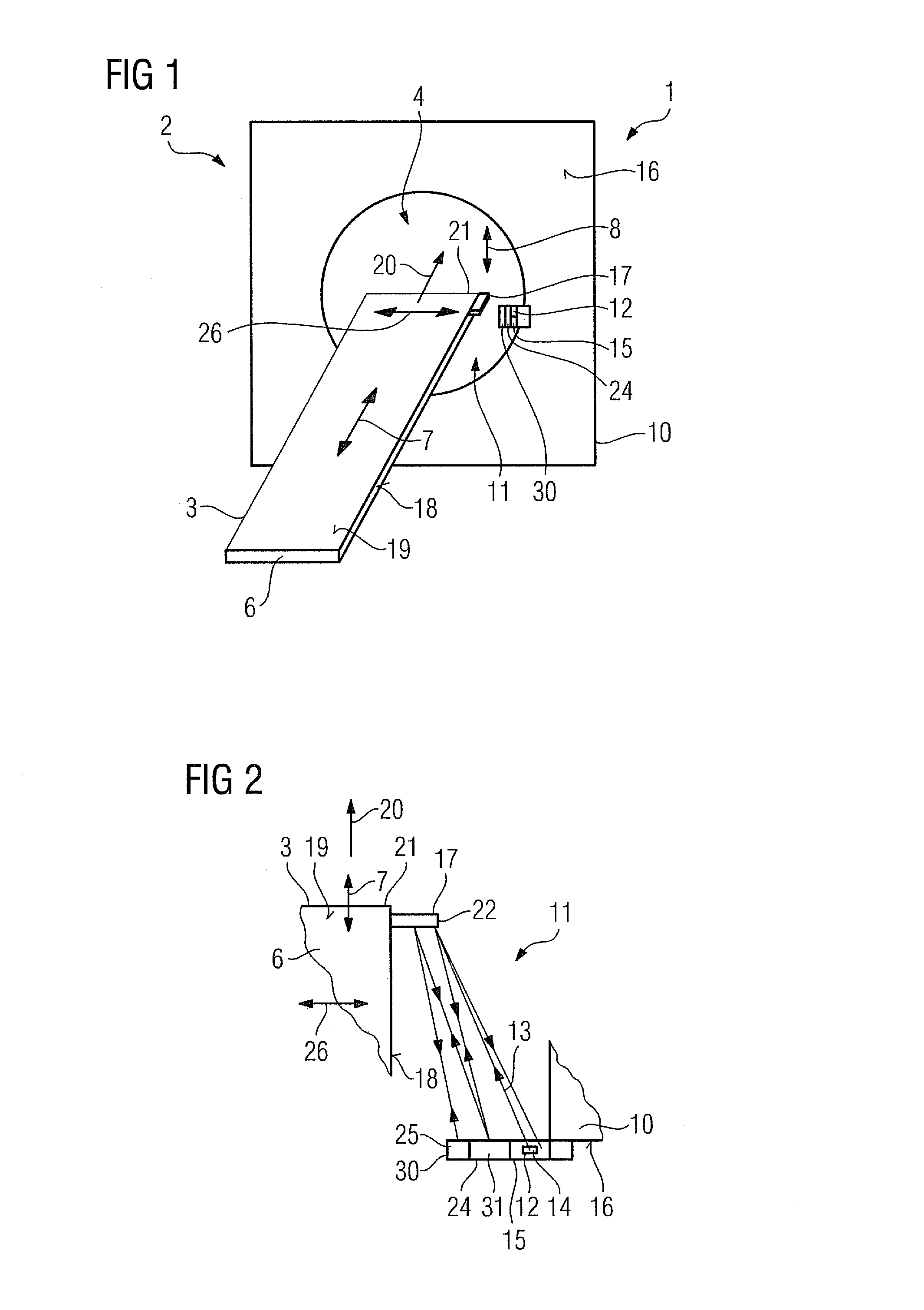
[0031]An inventive medical imaging facility 1, which is formed by a magnetic resonance tomography device 2, is shown in FIG. 1. The magnetic resonance tomography device 2 includes a magnet not shown in any greater detail for generating a strong and constant magnetic field. Furthermore the magnetic resonance tomography device 2 features gradient coils not shown in any greater detail which are provided for generation of a linear gradient field and high-frequency coils not shown in any greater detail. In addition the magnetic resonance tomography device 2 has an imaging area for recording images of an object under examination and / or of a patient for an imaging examination. In an alternate embodiment of the invention the medical imaging facility 1 can also be formed by a computer tomography device and / or a PET device.

[0032]The medical imaging facility 1 also includes a transport device 3 which includes a patient table 6 and is disposed to enable it to be moved in a z direction 7. The z ...


PUM


Abstract

A medical imaging facility has a transport device which is able to be moved at least partly in at least one direction. A position detection device has at least one transmit element which detects the position of the transport device and sends out a position measurement beam. The position detection device has at least one detector element and at least one reflector element.

Description

CROSS REFERENCE TO RELATED APPLICATIONS[0001]This application claims priority of German application No. 10 2009 054 916.1 filed Dec. 18, 2009, which is incorporated by reference herein in its entirety.FIELD OF THE INVENTION[0002]The invention relates to a medical imaging facility and a measurement method for detecting a position of a transport device of the medical imaging facility.BACKGROUND OF THE INVENTION[0003]A medical imaging facility with a transport device able to be moved in at least one direction is already known. The medical imaging facility, for example a magnetic resonance tomography device, a computed tomography device and / or a PET device, is a highly accurate system which demands a precise detection of the position of the transport device to enable a treatment and / or an examination to be undertaken. In this procedure a patient is moved into an imaging area of the medical imaging facility, with the transport device preferably comprising a transport table which is arran...

Claims


Application Information

Patent Timeline
Patent Type & Authority Patents(United States)
IPC IPC(8): A47B13/00
CPCA61B5/0555A61B6/547G01S5/16A61B5/055
Inventor GROSS, PATRICK
Owner SIEMENS HEALTHCARE GMBH
Why Eureka
Try Eureka