Fixing device and image forming device

a technology of fixing device and fixing device, which is applied in the direction of instruments, electrographic process devices, optics, etc., can solve the problems of shortening generating unusual noise, and reducing the rotation speed gradually, so as to prevent the generation of stick-slip noise, accurate control of the rotation speed, and suppress the shortening of the life of the fixing device

Active Publication Date: 2022-08-02
KONICA MINOLTA INC
View PDF8 Cites 1 Cited by
  • Summary
  • Abstract
  • Description
  • Claims
  • Application Information

AI Technical Summary

Benefits of technology

[0013]The present disclosure is made in view of the above technical problems, and an object of the present disclosure is to provide a fixing device capable of suppressing stick-slip noise as much as possible without causing life-shortening during stopping of idling rotation, and to provide an image forming device including the fixing device.
[0014]Further, an object of the present disclosure is to provide the fixing device capable of accurately controlling rotation speed during idling to prevent generation of stick-slip noise, while suppressing shortening of life of the fixing device as much as possible, and to provide the image forming device including the fixing device.

Problems solved by technology

The nip forming rotating bodies are structured so that only one rotating body (typically the pressure rotating body) has a rotational drive and the other rotating body is driven, and therefore during idling rotation when a sheet is not passing through, minute slips occur intermittently in the elastic layers of the nip between the rotating bodies, a phenomenon known as “stick-slip”, and this may generate unusual noise.
When unusual noise is generated it can be very jarring, especially in a quiet office, and may lead to a misunderstanding that the image forming device is malfunctioning, and therefore generation of such unusual noise is preferably suppressed as much as possible.
However, idling rotation is stopped after a defined time elapses, for example 15 seconds, but when rotation is suddenly stopped from a relatively high speed, for example 100 mm / s, damage to material of the nip forming rotating bodies is large and this leads to a shortening of the life of the fixing device, and therefore rotation speed is usually reduced gradually.
Further, according to the structure disclosed in Japanese Patent Application Publication No. 2008-20533, rotation speed of the nip forming rotating bodies is mechanically increased during idling without specific consideration of stick-slip occurrence, and therefore unnecessary increase in travel distance of the nip forming rotating bodies, increased wear and deterioration of elastic properties of the material, and shortened life of the fixing device are unavoidable.
According to Japanese Patent Application Publication No. 2017-107086, a total number of past jobs and a number of sheets passing through are stored, and a value of total jobs divided by number of sheets (average number of jobs per sheet) is stored, and idling rotation speed is changed based on these values, but even in this case, stick-slip generation conditions are not sufficiently evaluated, and unnecessary high speed rotation leads to a shortened lifespan.

Method used


Image

  • Fixing device and image forming device
  • Fixing device and image forming device
  • Fixing device and image forming device

Examples


embodiment 1

[0036]The following is a description of a tandem type color printer (hereinafter simply referred to as “printer”), described with reference to the drawings as an example of an image forming device pertaining to Embodiment 1 of the present disclosure.

[0037]1. Overall Structure of Printer

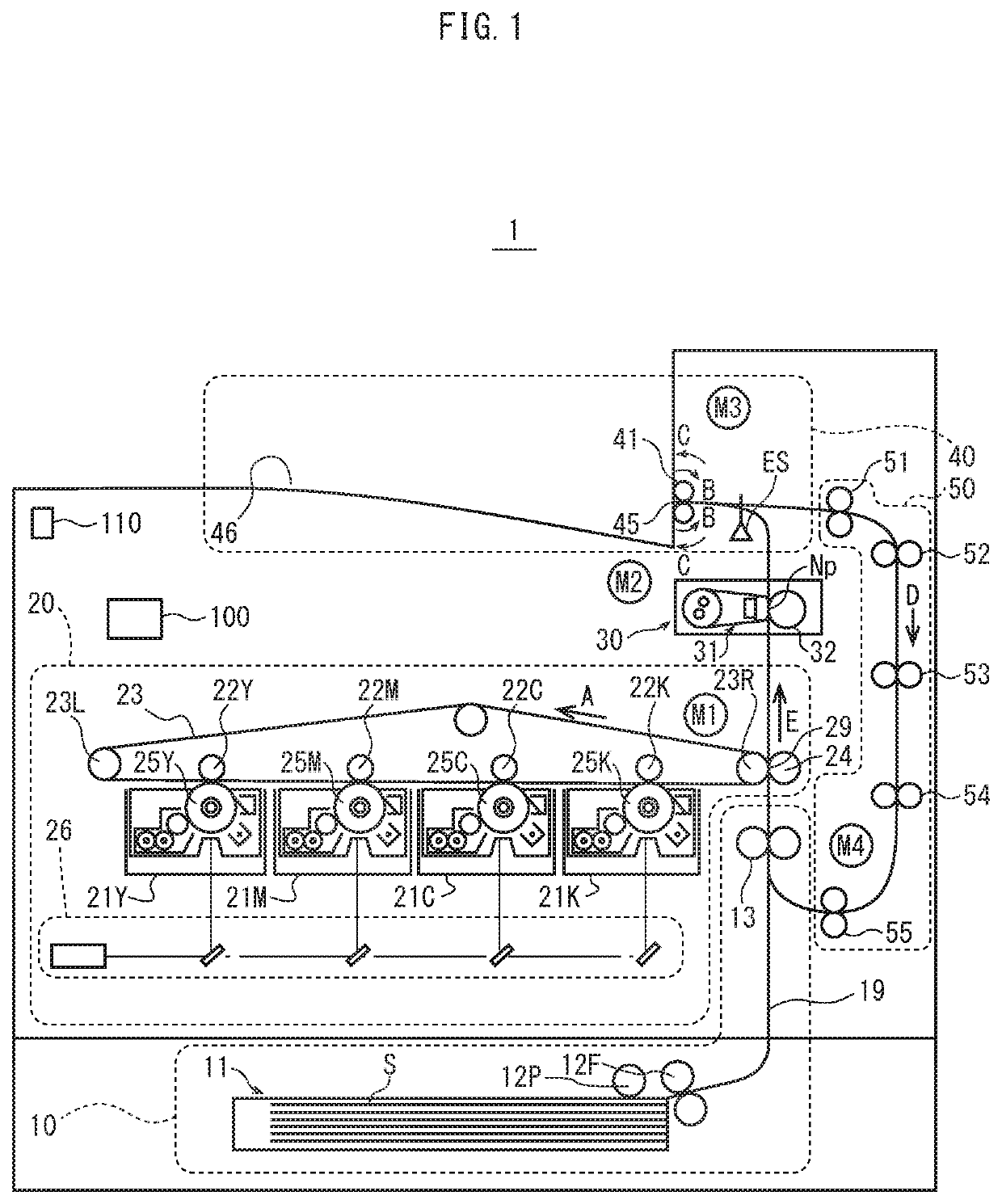
[0038]FIG. 1 is a schematic cross-section diagram illustrating an overall structure of a printer 1.

[0039]As illustrated, the printer 1 uses an electrophotographic system, includes a feeding section 10, an imaging section 20, a fixing section 30, an ejecting section 40, and a double-sided conveying section 50, and can execute single-sided print jobs that print an image on only one side (front side) of a sheet S and double-sided print jobs that print images on both sides (front side and back side) of a sheet S.

[0040]The feeding section 10 includes a sheet feed tray 11 that accommodates sheets S, a feeding roller 12P provided to the sheet feed tray 11 that feeds out the sheets S one by one to a conveyanc...

embodiment 2

[0202]Embodiment 2 according the present disclosure has the same hardware structure as Embodiment 1, and only content of a control of rotation speed of the fixing belt 311 during idling rotation (hereinafter also referred to as “idling rotation speed control”) is different, and therefore description of Embodiment 2 is based on only a flowchart of content of the idling rotation speed control.

[0203]The present embodiment also indicates rotation speed not in rpm, but in a travel speed of millimeters per second.

[0204]FIG. 13 is a flowchart illustrating operations of the idling rotation speed control executed by the controller 100.

[0205]First, whether or not it is time for idling rotation to start is determined (step S31). According to the present embodiment, idling rotation is performed when the device is powered on, when a print job is received, during warm-up from standby mode to increase temperature of the fixing belt 311 to a fixing temperature, and immediately after a fixing job to...


PUM


Abstract

A fixing device including: a heating rotating body; a pressure member pressed against the heating rotating body to form a nip; a first acquisition unit that acquires a first index value indicating a change in coefficient of friction between the heating rotating body and the pressure member; a second acquisition unit that acquires a second index value indicating a change in rigidity of an elastic layer in the heating rotating body and / or the pressure member; and a controller that executes at least one of two controls according to the index values: a first control during idling rotation after fixing job execution, for controlling temperature of the heating rotating body and time from a start of the idling rotation to an end of the idling rotation and a second control during idling rotation before and / or after fixing job execution, for controlling rotation speed of the heating rotating body.

Description

[0001]This application claims priority to Japanese Patent Applications No. 2020-135201, filed on Aug. 7, 2020, and No. 2020-135202, filed on Aug. 7, 2020 the contents of which are hereby incorporated herein by reference in their entirety.BACKGROUND(1) Technical Field[0002]The present disclosure relates to fixing devices that thermally fix unfixed images on sheets, and image forming devices including such fixing devices.(2) Description of the Related Art[0003]An electrophotographic image forming device includes a fixing device for thermally fixing an unfixed toner image formed on a sheet. The fixing device has a structure in which a pressure rotating body is pressed against the circumferential surface of a heated rotating body heated by a heat source to form a nip, and a sheet carrying an unfixed toner image is passed through the nip.[0004]A width of the nip in the sheet passing direction (hereinafter also referred to as “nip width”) is required to have a defined size so as not to ca...

Claims


Application Information

Patent Timeline
Patent Type & Authority Patents(United States)
IPC IPC(8): G03G15/20
CPCG03G15/205G03G15/2039G03G15/2017G03G15/2032G03G15/2064G03G2215/2038
Inventor OTSUKA, YUTAKASATO, TOMOYA
Owner KONICA MINOLTA INC
Why Eureka
Try Eureka