
Integrated smart helmet and methods and systems of controlling smart helmet

a helmet and smart technology, applied in the field of helmet systems and technology, can solve problems such as obstructing the field of view, and user habits affecting the safety of helmets

Active Publication Date: 2022-08-09
QUINTESSENTIAL DESIGN INC
View PDF3 Cites 0 Cited by
  • Summary
  • Abstract
  • Description
  • Claims
  • Application Information

AI Technical Summary

Benefits of technology

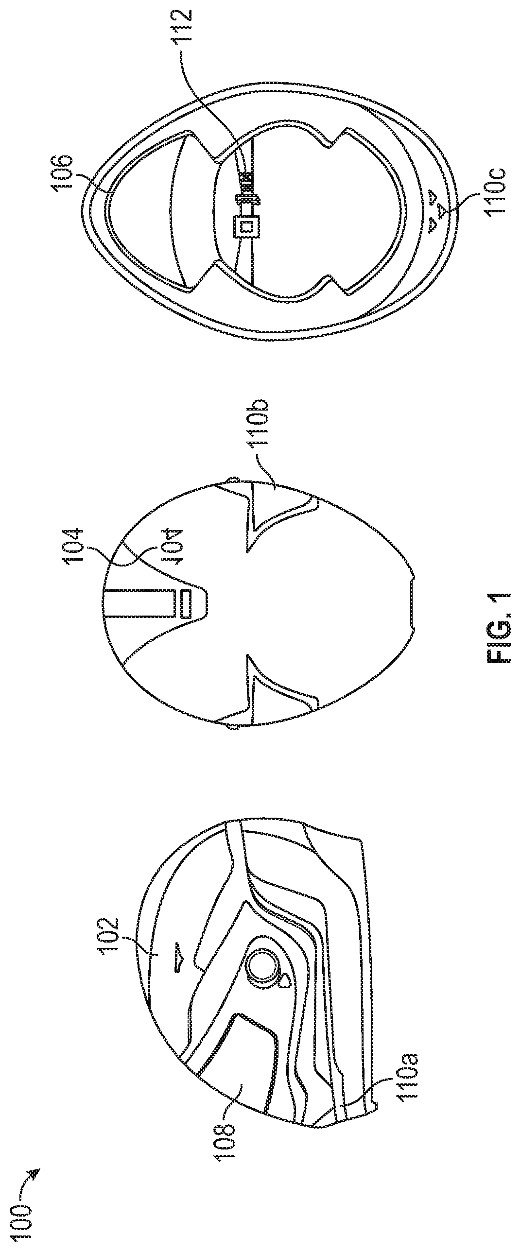
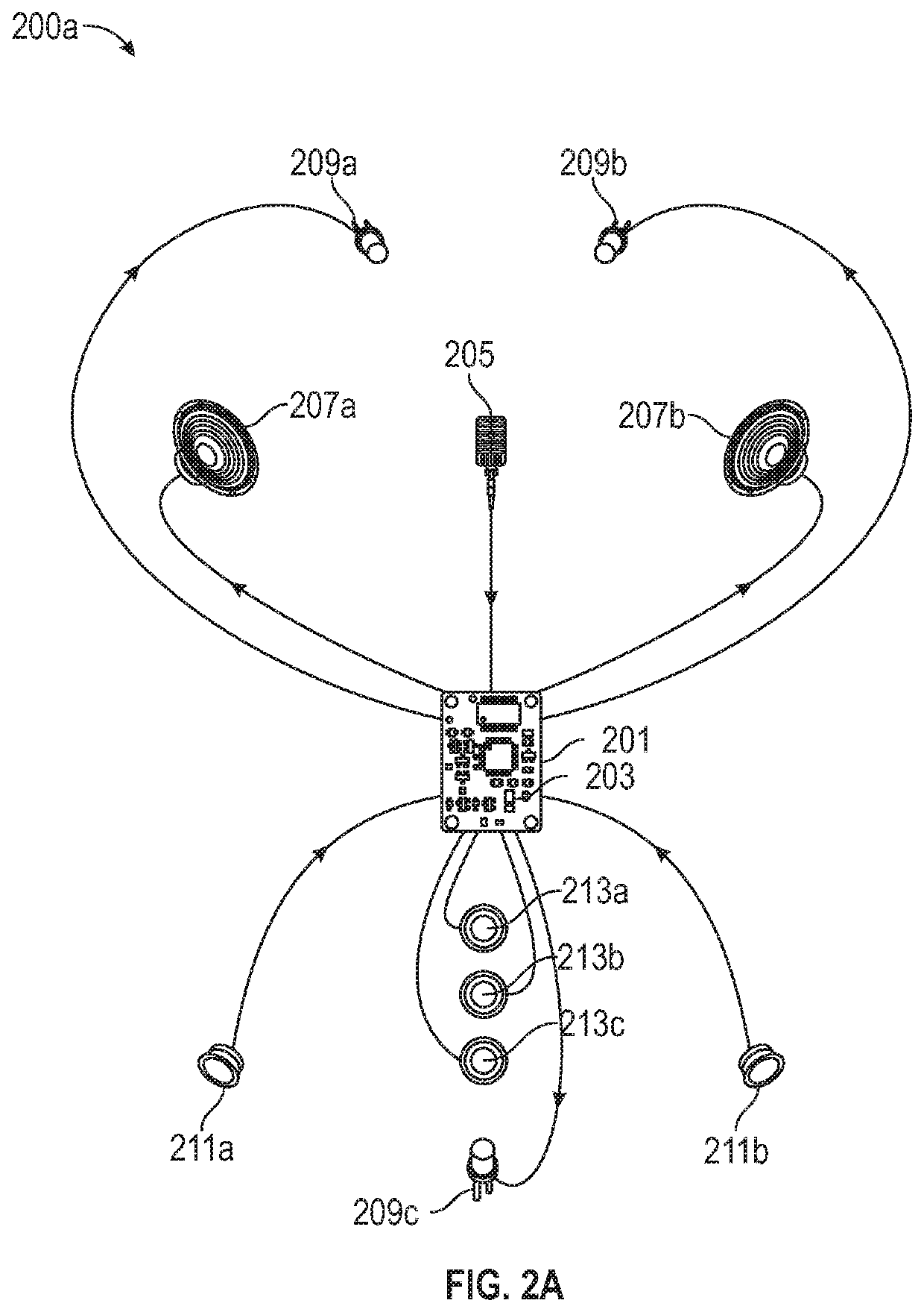
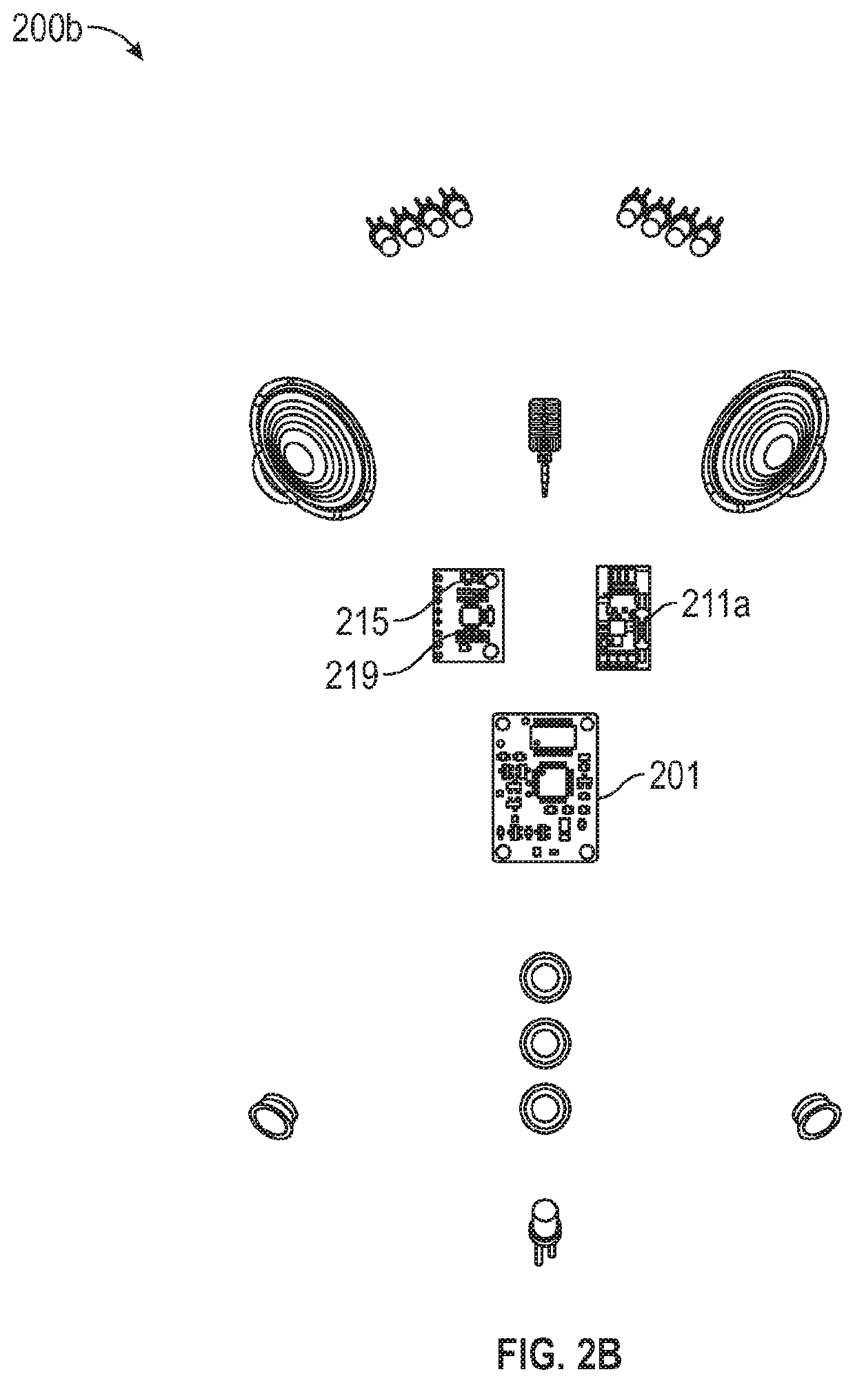
[0036]An objective of the present disclosure is directed towards providing a helmet further comprising a three axis digital gyroscope mounted in the housing which produces and records data which can be used to calculate where the user is looking at any given point of time by referencing it to the relative mean head position of the user. When combined with the accelerometer, the system can detect the exact “x,y,z” location of a helmet and the angle relative to its riding position. In the event of a rapid deceleration possibly indicating an accident, provides an algorithm that will contact emergency responders if the user is nonresponsive. The smart helmet system leverages the accelerometer in the computing device to cross check and verify the crash detected by the helmet. If both sensors don't register the same deceleration upon impact, the app can establish that it was just the helmet which suffered the impact by falling off the table, etc. The helmet further includes ultrasonic sensors which are placed at blind spot detection angles and are configured to scan and report if any object / vehicle is in the user's blind spot. Once there is an obstruction, an immediate sensory feedback is sent to the user via Led / vibration / etc. This enables the user to navigate the lanes on the road without having to take their eyes off the road. The helmet further comprises of an accelerometer, which will be used to gather data which can ascertain the acceleration / deceleration of the user and any sudden impacts to the helmet and user. This data is collected and can be factored into a series of protocols for crash detection.
[0038]An objective of the present disclosure is directed towards providing a data processing module that computes and stores data from the helmet system by leveraging the processing power of the user's computing device, thereby reducing the need for placing batteries in the helmet, resulting in a lighter and safer helmet system.
[0039]An objective of the present disclosure is directed towards providing a method and system for detecting, monitoring and / or controlling one or more of mobile services for a user's mobile device, and when the device is being used and the vehicle, operated by the user of the device, is moving. The present method and system determines whether the vehicle is being operated by a user that may also have access to a mobile communication device which, if used concurrently while the vehicle is in operation, may lead to unsafe operation of the vehicle. The present disclosure provides an algorithm to determine that a vehicle operator has potentially unsafe access to a mobile communication device by using the light sensor on the front of the computing device to sense if the user has the computing device out of his pocket for example. This combined with the speed of the user (calculated via movement on a mobile application) and the usage of buttons and user experience design can prompt the user to put away the computing device while driving and disable certain dangerous functions, or may restrict operator access to one or more services that would otherwise be available to the operator via the computing device.
[0041]An objective of the present disclosure is directed towards providing a method and system for activating and initiating an emergency distress protocol / signal by which the smart helmet system automatically begins recording and keeping a log of all the data which it receives so that this data can later be used in case of an enquiry, thereby acting as a deterrent for potential offenders.
[0042]An objective of the present disclosure is directed towards providing a method and algorithm to match the route of the user to the predictive weather data. Furthermore, the algorithm may be used to predict the weather during the entire ride rather than just at the beginning or at present. This would help user's be better prepared while doing longer activities where weather conditions could change with geographical locations. Map data is also used for Geo-locating the user during SOS and crash Protocols.
[0045]According to an exemplary aspect, an integrated smart helmet system comprising a control unit-PCB is wirelessly connected to a computing device over a network, the computing device is configured to enable a user to use different functionalities without having to remove a helmet and access the computing device and the control unit-PCB is configured to detect crashes while wearing the helmet by the user and notify the crash detected information to the computing device over the network.

Problems solved by technology

For example, as cycling and motorcycling have grown in popularity, so has the injuries resulting from accidents involving cycling or motorcycling.
Helmets are meant to safeguard user's but user habits compromise the safety of helmets.
The unsafe practices include disregard of a user to wear a helmet, non-strapping of helmets, using worn out helmets, using mobile phones or other communication devices while riding, turning of the user's head to check for obstacles thereby obstructing the field of view.
There are currently many intelligent helmet systems that address one or many of these issues, but fail to address all of them.
However, these devices are bulky and leave loose wires hanging around the helmet making them inconvenient and non-aesthetic.
Furthermore, the weight from these external devices can affect the natural head tilt and response time of the user.
Some of these well-known systems carry a transmitting unit within the helmet, but have the disadvantage of using an umbilical cord to a base unit.
Such a unit is not a complete and self-contained system.
Still other known units do not provide a proper cushioning for the electronics itself.
Consequently, the electronics may be damaged from impact to the helmet.
However, these helmets involve a lot of processing due to use of image processing cameras and hence are costlier.
Also these helmets (Skully) have display screens in the visors, which might distract the driver from driving and can be intrusive and unsafe.
However, the helmets described in the prior art are passive and fail to be responsive to the user's environment.

Method used


Image

  • Integrated smart helmet and methods and systems of controlling smart helmet
  • Integrated smart helmet and methods and systems of controlling smart helmet
  • Integrated smart helmet and methods and systems of controlling smart helmet

Examples


Embodiment Construction

[0067]It is to be understood that the present disclosure is not limited in its application to the details of construction and the arrangement of components set forth in the following description or illustrated in the drawings. The present disclosure is capable of other embodiments and of being practiced or of being carried out in various ways. Also, it is to be understood that the phraseology and terminology used herein is for the purpose of description and should not be regarded as limiting.

[0068]The use of “including”, “comprising” or “having” and variations thereof herein is meant to encompass the items listed thereafter and equivalents thereof as well as additional items. The terms “a” and “an” herein do not denote a limitation of quantity, but rather denote the presence of at least one of the referenced item. Further, the use of terms “first”, “second”, and “third”, and the like, herein do not denote any order, quantity, or importance, but rather are used to distinguish one ele...


PUM


Abstract

Exemplary embodiments of the present disclosure are directed towards an integrated smart helmet system, comprising: a control unit-PCB 201 is wirelessly connected to a computing device 303 over network 305, computing device 303 is configured to enable a user to use different functionalities without having to remove helmet 102 and access the computing device 303 and the control unit-PCB 201 is configured to detect crashes while wearing the helmet 102 by the user and notify crash detected information to computing device 303 over network 305, buttons 213a-213d are positioned at the rear or side of helmet 102 and control unit-PCB 201 is electrically coupled to buttons 213a-213d, buttons 213a-213d are configured to initiate prompts to direct the user to put away the computing device 303 while driving and disable certain dangerous functions.

Description

TECHNICAL FIELD[0001]The present disclosure generally relates to the field of helmet systems and technology, and more particularly to a smart helmet that has integrated electronics and systems which actively monitors a user's environment and provides various kinds of information to the user.[0002]More particularly, the present disclosure relates to a combination of a helmet, and a controller, and a mobile phone device application, with enhanced features, including but not limited to:[0003]a. built-in LED turn signals;[0004]b. positive audible feedback for the signals;[0005]c. fully integrated Bluetooth and phone communication system;[0006]d. hands-free cellular communications;[0007]e. fully integrated headphone and microphone;[0008]f. gyroscope sensor;[0009]g. ultrasonic radar sensor;[0010]h. accelerometer;[0011]i. helmet remote;[0012]j. processing system for helmet;[0013]k. crash detection systems;[0014]l. Concussion detection;[0015]m. Rise-to-wake;[0016]n. mobile phone application...

Claims


Application Information

Patent Timeline
Patent Type & Authority Patents(United States)
IPC IPC(8): A42B3/04H04W4/90G01S19/17H04B1/3827H04W76/14B62J43/30B62K23/02
CPCA42B3/046G01S19/17H04B1/385H04W4/90B62J43/30B62K23/02H04B2001/3866H04W76/14
Inventor VENKATA JAGANNADHA RAO, ANIRUDHA SURABHI
Owner QUINTESSENTIAL DESIGN INC
Learn More